High-energy multi-state low-temperature ionizer

A low-temperature plasma and generator technology, applied in the direction of plasma, can solve the problems of poor cooling effect, difficult ion control, complex ion generator structure, etc., and achieve the effect of avoiding burning

Inactive Publication Date: 2012-01-25
陈固明 +1
View PDF8 Cites 10 Cited by
  • Summary
  • Abstract
  • Description
  • Claims
  • Application Information

AI Technical Summary

Problems solved by technology

Although the above-mentioned methods can all achieve a certain purpose of sterilization and deinsectization, various methods are all limited in their use due to their own defects, such as the most widely used ethylene oxide gas sterilization at present, Its advantage is that there is no high temperature and high pressure, the temperature is only 40~60°C, and it is not easy to damage the sterilized items. The disadvantage is that ethylene oxide is flammable, explosive, and highly toxic, which will pollute the environment and cause cancer to the human body. At the same time, it is expensive. Disinfection takes a long time, and after disinfection, it will be placed for several days to detoxify, etc.
[0003] Wit

Method used


Image

  • High-energy multi-state low-temperature ionizer
  • High-energy multi-state low-temperature ionizer

Examples


Embodiment 1

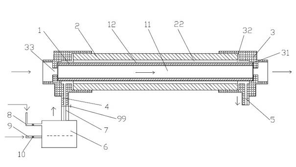
[0017] The structural representation of the high-energy multi-state low-temperature plasma generator of the present invention is as attached figure 1 As shown, the inner electrode 1 and the outer electrode 2 are included, and the inner electrode 1 and the outer electrode 2 are respectively connected to a high-frequency high-voltage power supply. The inner electrode 1 and the outer electrode 2 are tubular structures, and the hollow cavity of the inner electrode 1 is used as a cooling channel 11. The two ends of the inner electrode 1 and the outer electrode 2 are respectively provided with electrode holders 3, and the two ends of the inner electrode 1 and the outer electrode 2 are respectively fixed on the electrode holders 3, the inner electrode 1 is set inside the outer electrode 2, and the outer surface of the inner electrode 1 is in contact with the An ionization channel 22 is formed between the inner surfaces of the outer electrodes 2. The ionization channel 22 is suitable f...

Embodiment 2

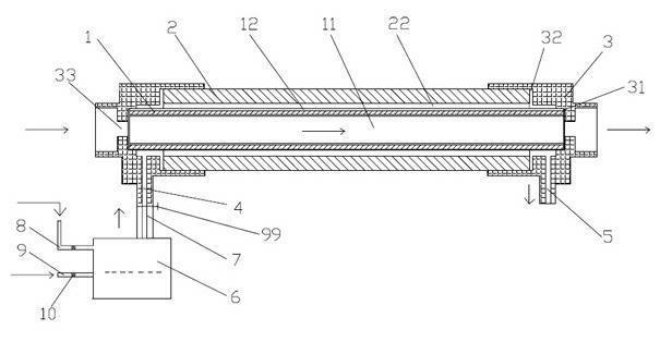
[0024] The structure of this embodiment is similar to that of Embodiment 1, and the difference is that an insulating layer 12 is also provided on the inner and outer surfaces of the outer electrode 2 to further ensure the insulation reliability between the inner electrode 1 and the outer electrode 2, wherein the material of the insulating layer 12 Also for ceramics.

[0025] The working process of this embodiment is the same as that of Embodiment 1.


PUM


Abstract

The invention discloses a high-energy multi-state low-temperature ionizer, comprising an internal electrode and an external electrode, wherein the internal electrode and the external electrode are respectively connected with a power supply. The internal electrode and the external electrode are both tubular structures, and a hollow cavity of the internal electrode is a cooling channel; two ends of the internal electrode and two ends of the external electrode are respectively provided with an electrode support, and the two ends of the internal electrode and the two ends of the external electrode are respectively fixed on the electrode support; the internal electrode is sleeved in the external electrode, and an ionization channel is formed between the external surface of the internal electrode and the internal surface of the external electrode; two ends of the ionization channel are respectively provided with an aerial fog input port and an aerial fog output port, and the aerial fog input port and the aerial fog output port are respectively communicated with the ionization channel. The ionizer provided by the invention is simple in structure and convenient to use, the cooling channel is formed at the center of the internal electrode, when working, the cooling channel can cool the ionization channel so as to generate a large amount of low-temperature plasmas, the cooling effect is better, and the generated plasmas have high energy charge.

Description

technical field [0001] The invention is an ion generator, especially a high-energy multi-state low-temperature plasma generator. Background technique [0002] At present, the methods commonly used for disinfection and sterilization of articles and medicines at home and abroad mainly use high temperature and high pressure steam sterilization, ethylene oxide gas sterilization, ionizing radiation sterilization, ultraviolet rays, infrared rays, microwave sterilization, etc. Although the above-mentioned methods can all achieve a certain purpose of sterilization and deinsectization, various methods are all limited in their use due to their own defects, such as the most widely used ethylene oxide gas sterilization at present, Its advantage is that there is no high temperature and high pressure, the temperature is only 40~60°C, and it is not easy to damage the sterilized items. The disadvantage is that ethylene oxide is flammable, explosive, and highly toxic, which will pollute the ...

Claims


Application Information

Patent Timeline
IPC IPC(8): H05H1/46
Inventor 陈固明周永佳
Owner 陈固明
Why Eureka
Try Eureka