
Large-sized precise direct-driving main shaft structure

A large-scale, spindle technology, used in metal processing equipment and other directions, can solve the problems of short service life, small bearing capacity, low precision, etc., and achieve the effects of good vibration absorption, long service life and high precision

Inactive Publication Date: 2012-02-01
宝鸡忠诚机床股份有限公司
View PDF7 Cites 8 Cited by
  • Summary
  • Abstract
  • Description
  • Claims
  • Application Information

AI Technical Summary

Problems solved by technology

[0003] The key to realize the high-speed and precision electric spindle is the application of precision bearings. At present, precision angular contact ball bearings and precision cylindrical roller bearings are mainly used in high-speed precision electric spindles. However, compared with dynamic and static pressure bearings, the carrying capacity of these bearings Small, low precision, short service life
Although there are a small number of spindle structures using hydrodynamic and static pressure bearings, gas dynamic and static pressure bearings and magnetic suspension bearings, their specifications are relatively small

Method used


Image

  • Large-sized precise direct-driving main shaft structure
  • Large-sized precise direct-driving main shaft structure
  • Large-sized precise direct-driving main shaft structure

Examples


Embodiment Construction

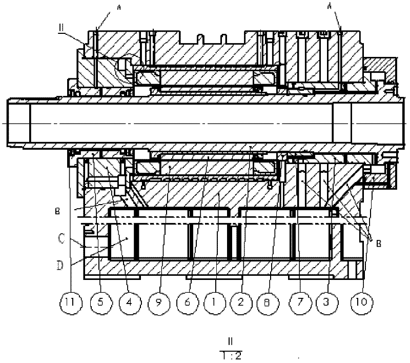
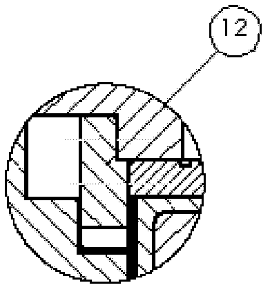
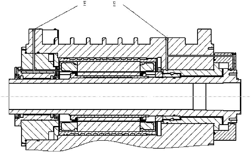
[0012] Such as Figure 1-3 Specific embodiments of the invention are given. The main inventive points of the present invention are: liquid dynamic and static pressure spindle technology and structure; built-in electric spindle technology and structure. The specific implementation plan is:

[0013] The outer ring of the front hydrostatic bearing fits with the hole of the spindle box, and the inner diameter matches the outer diameter of the main shaft; there is a thrust ring between the front hydrostatic bearing and the main shaft; the outer ring of the rear hydrostatic bearing fits with the inner hole of the rear bearing housing, and the inner diameter matches The outer diameter of the main shaft is coordinated; the motor is arranged between the front and rear hydrostatic bearings; the corresponding holes in the main shaft box are used as the oil inlet and outlet of the hydrostatic bearing, and the coolant inlet and outlet of the electric spindle.

[0014] The rotor of the mo...


PUM


Abstract

The invention relates to a large-sized precise direct-driving main shaft structure of a numerical control machine in the technical field of mechanical engineering, which comprises a main shaft structure formed by utilizing a liquid dynamic and static hydraulic technology and an electrical main shaft technology, and a precise direct-driving numerical control machine tool main shaft part which can realize large-sized liquid dynamic and static hydraulic bearings, wherein the precise direct-driving numerical control machine tool main shaft part is internally provided with a motor. The motor is arranged between the front dynamic and static hydraulic bearing and the rear dynamic and static hydraulic bearing; according to the direct-driving structure, the span of the bearings of the main shaft is increased; when the motor drives the main shaft to rotate, due to the external force action of a transmission link, the main shaft only bears the peripheral rotating torque without bearing the radial driving force, is more balanced due to no middle transmission impact during the high-speed operation of the main shaft, and the accuracy of a processed part is higher. The large-sized precise direct-driving main shaft structure has the advantages of high accuracy, large rigidity, long service life, good shock absorption property and vibration resistance, and excellent work stability and reliability, and can be used for the main shafts of precise processing machinery and the main shafts of high-speed and high-precise equipment.

Description

technical field [0001] The invention relates to a large-scale high-precision direct-drive spindle structure of a numerically controlled machine tool in the technical field of mechanical engineering. Background technique [0002] CNC machine tools are the mainstream products of the machine tool industry. High-speed precision CNC machine tools are one of the technical foundations and development directions of the equipment manufacturing industry, and are a strategic industry of the equipment manufacturing industry. The working performance of high-speed precision CNC machine tools depends first on the performance of high-speed precision spindles. The high-speed precision spindle system has always been one of the three high-tech CNC machine tools. In order to improve the spindle speed and machining accuracy, the built-in electric spindle has become the spindle of CNC machine tools. The best choice for structure. [0003] The key to realize the high-speed and precision electric ...

Claims


Application Information

Patent Timeline
IPC IPC(8): B23B19/02
Inventor 苏忠堂高利强李士船李玉朝
Owner 宝鸡忠诚机床股份有限公司
Learn More