
Rotor blade airplane with variable flight mode

A technology of rotating wing and flight mode, applied in the field of aviation aircraft, can solve problems such as difficult control, complex mechanical structure, large aircraft, etc., and achieve the effect of reducing interference, reducing interference, and small airflow interference

Active Publication Date: 2014-04-02
南京优翼航空科技有限公司
View PDF6 Cites 3 Cited by
  • Summary
  • Abstract
  • Description
  • Claims
  • Application Information

AI Technical Summary

Problems solved by technology

[0004] The canard rotary-wing aircraft solved the problems such as the complex mechanical structure of the tilt-rotor aircraft, but the successive crashes of two "Dragonfly" demonstrators showed that there are still many serious problems in the currently disclosed technical solutions of the canard rotary-wing aircraft. Problems, especially when the aircraft is flying in the rotor flight mode and the transition process, there will be strong airflow interference between the downwash airflow of the rotating wing and the tail, which will cause the aircraft to generate large and uncontrollable unsteady and nonlinear aerodynamic loads

Method used


Image

  • Rotor blade airplane with variable flight mode
  • Rotor blade airplane with variable flight mode
  • Rotor blade airplane with variable flight mode

Examples


Embodiment Construction

[0024] Describe the present invention below in conjunction with specific embodiment:

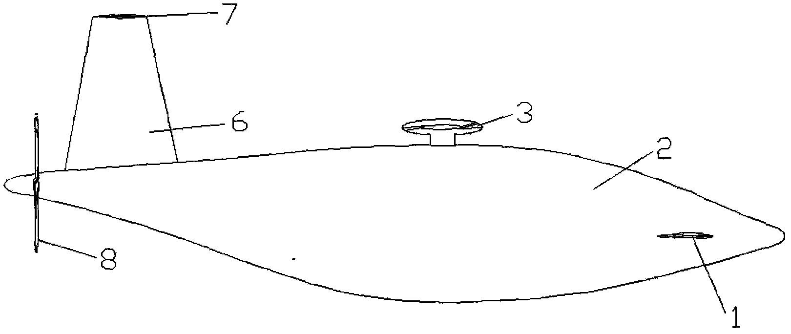
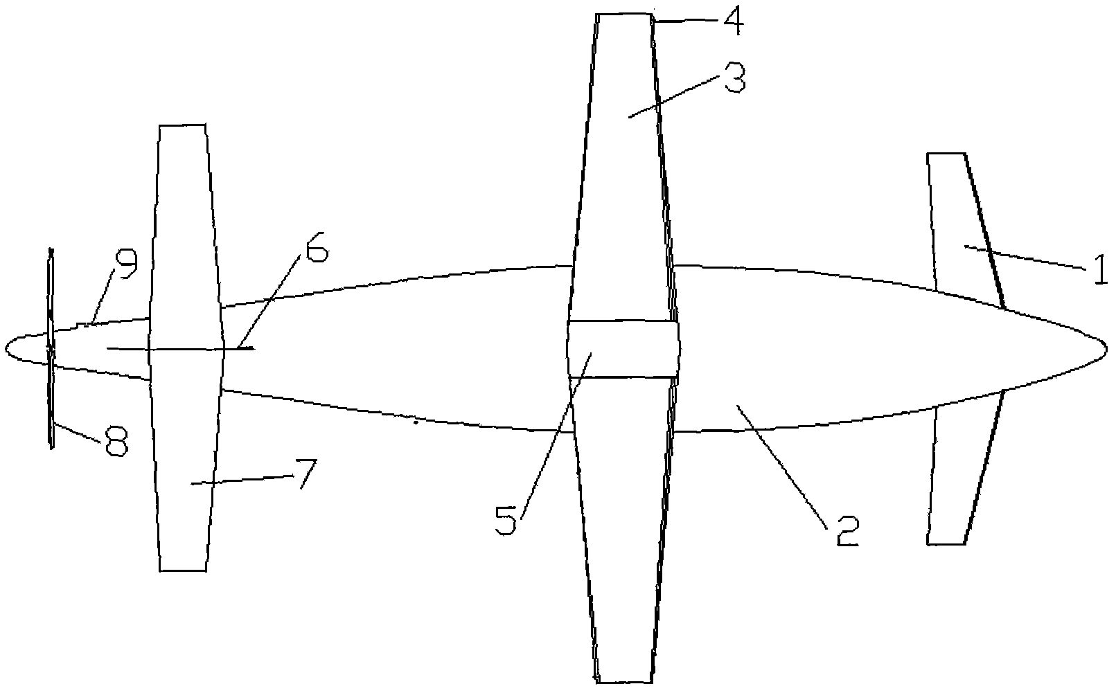
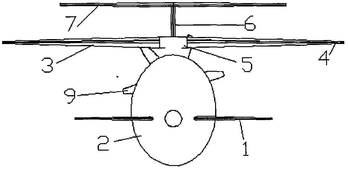
[0025] This embodiment is an unmanned verification machine of a rotary-wing aircraft with variable flight modes, and the designed take-off gross weight of the aircraft is 466kg. The flight mode is: when the aircraft takes off, the rotor flight mode is adopted, and the rotary wing drive system drives the rotary wing 3 to rotate at a high speed, so that the aircraft takes off vertically from the ground and flies forward at a low speed; when the flight speed reaches the conversion speed, the rotary wing 3 is unloaded And the rotating wing 3 is locked as a fixed wing through the rotating wing swinging lock-release mechanism and the rotating wing rotating lock-release mechanism. In this process, the canard 1 and the horizontal tail 7 provide lift as the main lifting surface, and the aircraft forward power system provides the aircraft The power of the forward flight enters the fixed-wing flight mo...


PUM


Abstract

The invention provides a rotor blade airplane with a variable flight mode, comprising an airplane body, a plurality of canards, a rotor blade, an empennage and a power system. The rotor blade airplane is characterized in that the canards are symmetrically arranged at two sides of the head of the airplane body; the empennage comprises a perpendicular empennage and a horizontal empennage, the perpendicular empennage is arranged at the back of the airplane body, and the horizontal empennage is arranged at the top end of the perpendicular empennage to form into the 'T'-shaped empennage; the canards, the rotor blade and the horizontal empennage are distributed with one another in the manner of a step from low to high along with the Z direction of the airplane; and a plurality of high lift devices are arranged on the canards and the horizontal empennage, and the lift force requirement for the controllable flight of the airplane can be met by a lift force generated on the canards and the horizontal empennage during transition flight. The rotor blade airplane can prevent the empennage from being directly impacted by the downwash of the rotor blade under a rotor blade flight mode, the distraction to a horizontal tail caused by the downwash of the rotor blade can be reduced, and the airplane can be controlled under the rotor blade flight mode during the transition flight.

Description

technical field [0001] The invention relates to the technical field of aviation aircraft, in particular to a rotary wing aircraft with variable flight modes. Background technique [0002] Aircraft design researchers have always wanted to design an aircraft that has both high-speed flight and small space take-off and landing capabilities. Currently, in practical applications, relatively mature high-speed aircraft that can take off and land vertically are similar to the "Harrier" attack aircraft. Jet aircraft, and tilt-rotor aircraft like the V-22 Osprey. The "Harrier" aircraft has a conventional layout. It mainly uses the method of deflecting the engine nozzle and changing the thrust direction to achieve vertical take-off and landing. However, this implementation method consumes a lot of fuel and has high requirements on the engine. The aircraft load is limited during vertical take-off and landing. , the flight range and flight time are short; the tilt rotor aircraft uses th...

Claims


Application Information

Patent Timeline
Patent Type & Authority Patents(China)
IPC IPC(8): B64C27/22
Inventor 高正红詹浩邓阳平张怡哲白俊强夏露曹飞田力
Owner 南京优翼航空科技有限公司
Learn More