
Directional drilling signal transmission drill pipe

A signal transmission and directional drilling technology, applied in directional drilling, drill pipe, drill pipe, etc., can solve the problems of the ability of the drill pipe to withstand torque, the strength cannot be effectively guaranteed, and the assembly and maintenance of the drill pipe are unfavorable. Achieve the effects of reducing loss along the process, preventing damage to the thread profile, and simple structure

Active Publication Date: 2014-03-19
CHINA COAL TECH & ENG GRP CHONGQING RES INST CO LTD
View PDF8 Cites 2 Cited by
  • Summary
  • Abstract
  • Description
  • Claims
  • Application Information

AI Technical Summary

Problems solved by technology

[0004] First of all, the outer pipe of the existing drill pipe is often welded together by friction welding in sections, the strength cannot be effectively guaranteed, and it is prone to fracture damage during the drilling process, which affects the continuation of the work of the drill pipe;
[0005] Secondly, the threaded structure at both ends of the outer pipe of the drill pipe adopts a traditional double-cone structure. When the drilling process is subjected to a huge torque or bending moment, it is prone to over-positioning, which will cause damage to the threaded connection, making the drill pipe The ability to withstand torque is reduced, and even the drill cannot meet the requirements of drilling and is scrapped;
[0006] Again, the central cable connection structure of the existing drill pipe is an integral structure, which is not conducive to the assembly and maintenance of the drill pipe

Method used


Image

  • Directional drilling signal transmission drill pipe
  • Directional drilling signal transmission drill pipe
  • Directional drilling signal transmission drill pipe

Examples


Embodiment Construction

[0028] The specific implementation manners of the present invention will be described in detail below in conjunction with the accompanying drawings.

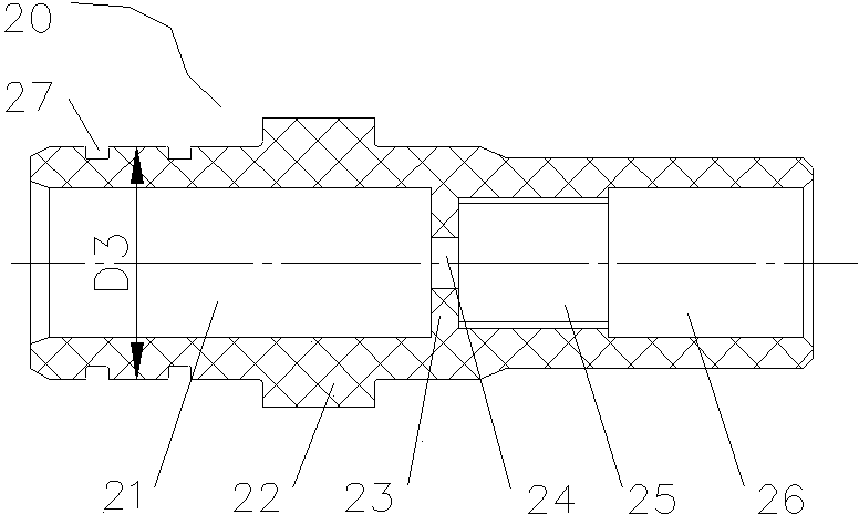
[0029] Such as figure 1 As shown, it is a schematic structural diagram of an embodiment of the directional drilling signal transmission drill pipe of the present invention. As shown in the figure, the directional drilling signal transmission drill pipe of this embodiment includes an outer pipe 10 and a locating frame erected in the outer pipe 10. In the cable assembly, the two ends of the outer tube 10 are respectively provided with mutually matching threaded connection structures, and the cable assembly includes a cable connector 20 and a cable connector 60 respectively arranged at the two ports of the outer tube 10, and respectively connected with the cable connector 20 and the cable connector 60. The core-protecting tube 40 fixedly connected to the tail of the inner side of the outer tube 10, the central cable 50 placed in th...


PUM


Abstract

The invention discloses a directional drilling signal transmission drill pipe, comprising an outer pipe and a cable assembly installed in the outer pipe by a positioning bracket, wherein both ends of the outer pipe are respectively provided with thread connection structures matched with each other; the cable assembly comprises a cable connector and a cable connection seat arranged at two ends of the outer pipe, a core protection pipe respectively and fixedly connected with the tails of the cable connector and the cable connection seat towards the inner side of the outer pipe, and a central cable arranged in the core protection pipe; the front part of the cable connector is embedded with a spring connector; the front part of the cable connection seat is embedded with a spring connection seat; the spring connection seat is fixedly provided with a spring, and the spring is pressed and fixed between the spring connection seat and the spring connector when two adjacent drill pipe units are connected; the spring connector and the spring connection seat are electrically connected with the central cable respectively; and the cable connector and the cable connection seat are respectively provided with a connection structure matched with each other.

Description

technical field [0001] The invention relates to a drill pipe, in particular to a coal mine directional drilling signal transmission drill pipe. Background technique [0002] Drill pipes are mainly used in the construction of deep wells, horizontal wells and extended-reach wells in the exploration and development of oil and gas and coal mines. It is required that they must be able to withstand huge internal and external pressure, twisting, bending and vibration. The drill pipe is a steel pipe with threads at the end, which can not only be used to connect and lengthen the drill pipes, but also can be used to connect the surface equipment of the drilling rig and the drilling and grinding equipment or bottom hole equipment at the bottom of the drilling well. Its purpose is to transport the drilling mud to drill, and together with the drill, raises, lowers or rotates the bottom hole device. During the mining and refining of oil and gas coal, the drill pipe can be used many times...

Claims


Application Information

Patent Timeline
Patent Type & Authority Patents(China)
IPC IPC(8): E21B17/042E21B7/04H02G15/06H02G15/18
Inventor 唐大勇张俞刁文庆王清峰谢北萍孙生吕冰尹登科王志红刘玉岩陈松林
Owner CHINA COAL TECH & ENG GRP CHONGQING RES INST CO LTD
Learn More