Articulation unit for robot and robot
A robot joint and joint technology, which is applied in the direction of manipulators, electrical components, electromechanical devices, etc., can solve the problems of joint unit miniaturization, light weight limitations, small and light weight difficulties, etc., to achieve miniaturization, ensure safety, and reduce costs Effect
- Summary
- Abstract
- Description
- Claims
- Application Information
AI Technical Summary
Problems solved by technology
Method used
Image
Examples
Embodiment 1
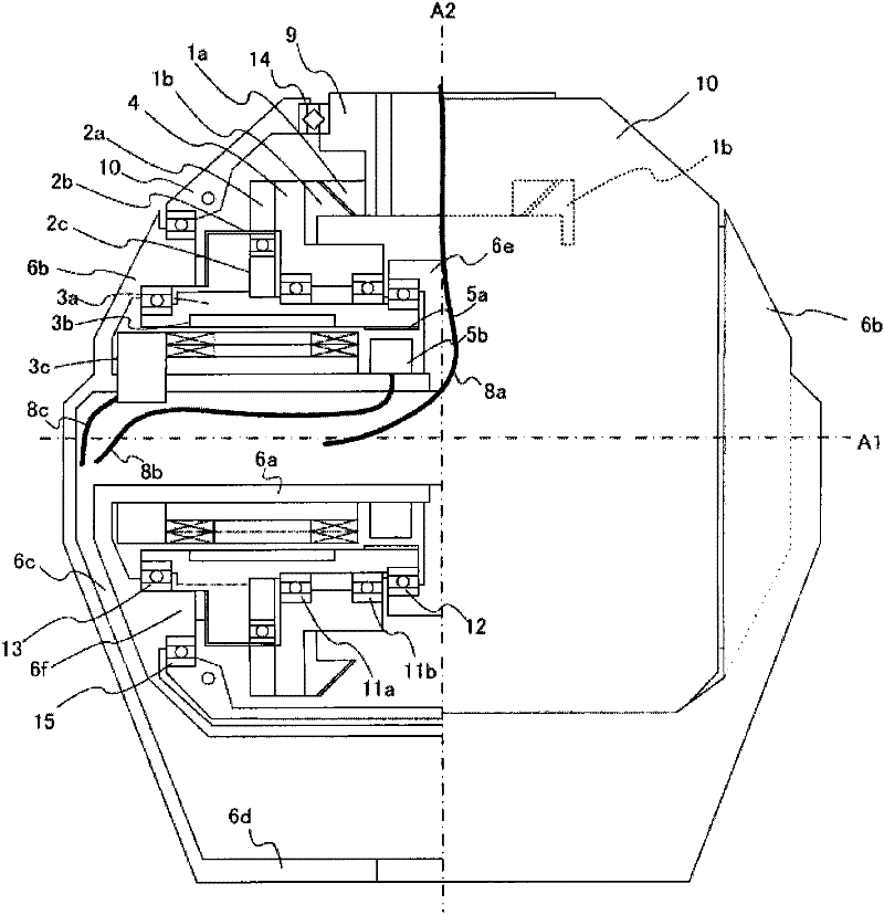
[0074] A first embodiment of the present invention will be described. Figure 4 It is an external view of the joint unit 36 according to this embodiment. The cover and support structure 10 rotates around the horizontal axis A1 around the support disk 6b, and the output body 9 rotates around the vertical axis A2.
[0075] figure 1 It is a sectional view of the differential joint unit of the present invention. In the figure, the bevel gear (output bevel gear) 1a rotates integrally with the output body 9, and is respectively driven by the rotation of a pair of motors (outer rotor motors) 3 described later (rotating shafts parallel to the axis A1) with respect to the vertical axis A2 A pair of bevel gears arranged symmetrically is the bevel gear 1b (a set of bevel gears).
[0076] On the support disk 6b, the following cylindrical portion 6e is formed. The cylindrical portion 6e forms a part of the outer contour of the joint unit 36, and is arranged to sandwich the pair of mo...
Embodiment 2
[0097] Next, a second embodiment of the present invention will be described. This embodiment has many points in common with the above-mentioned first embodiment, and in this embodiment, descriptions of the same structures as those of the first embodiment are omitted and the same symbols are used.
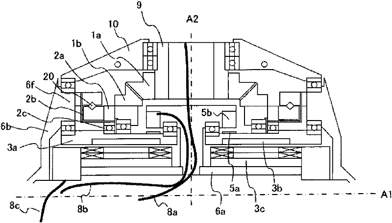
[0098] figure 2 It is a cross-sectional view showing another example of the joint unit of the present invention. Here, except for the support arm, the support base, and the output body, since it has a symmetrical structure with respect to the horizontal axis A2, only the upper half is shown for ease of illustration. In addition, in figure 2 In , for a pair of components arranged symmetrically on the left and right, the symbol is only marked on either side of the left and right.
[0099] In this embodiment, the radio wave generator 2c is integrated with the motor rotor 3a. 2b is a flexible gear, and the flange portion is different from that of Embodiment 1, and uses an outwardl...
Embodiment 3
[0102] Next, a third embodiment of the present invention will be described. This embodiment has many points in common with the above-mentioned first embodiment, and in this embodiment, descriptions of the same structures as those of the first embodiment are omitted and the same symbols are used.
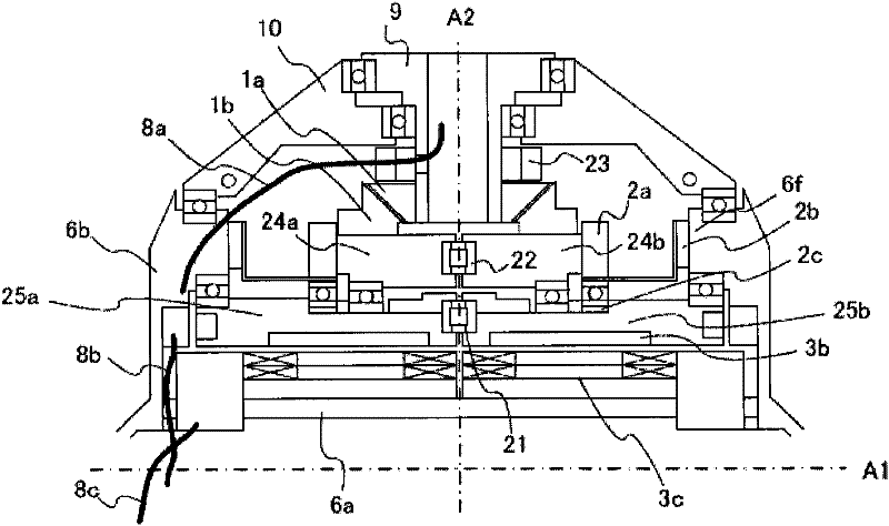
[0103] Such as image 3 As shown, except for the support arm, the support seat, and the output body, only the upper half is shown due to the roughly symmetrical structure with respect to the shaft. In addition, in image 3 In , for a pair of components arranged symmetrically on the left and right, the symbol is only marked on either side of the left and right.
[0104] 21 is a roller bearing, which supports axial and radial loads so that the left and right motor rotor cores 25a and 25b can rotate relative to each other around the horizontal axis.
[0105] Reference numeral 22 denotes a roller bearing, which similarly supports axial and radial loads such that left and right rotatin...
PUM
 Abstract
Description
Claims
Application Information
 - R&D
- Intellectual Property
- Life Sciences
- Materials
- Tech Scout
- Unparalleled Data Quality
- Higher Quality Content
- 60% Fewer Hallucinations
Browse by: Latest US Patents, China's latest patents, Technical Efficacy Thesaurus, Application Domain, Technology Topic, Popular Technical Reports.
© 2025 PatSnap. All rights reserved.Legal|Privacy policy|Modern Slavery Act Transparency Statement|Sitemap|About US| Contact US: help@patsnap.com


