Operating fuel tank

A technology of working fluid and container, which is applied in the field of working fluid container, and can solve problems such as pressure compensation element function hindrance

Active Publication Date: 2013-07-03
KAUTEX TEXTRON
View PDF7 Cites 0 Cited by
  • Summary
  • Abstract
  • Description
  • Claims
  • Application Information

AI Technical Summary

Problems solved by technology

The function of the pressure compensation element, in particular with the plug made of sintered material, is impeded if it is wetted by a liquid

Method used


Image

  • Operating fuel tank
  • Operating fuel tank
  • Operating fuel tank

Examples


Embodiment Construction

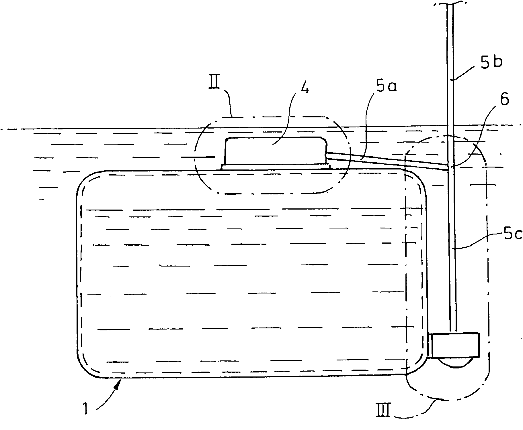
[0018] Reducing agent container 1, if it is in figure 1 As shown in, it can be composed of any material and made in any manner and method. However, the reducing agent container 1 is preferably composed of a thermoplastic and obtained by extrusion blow molding. The reducing agent container can be arranged concealed in the rear area of ​​the motor vehicle body or in the engine compartment of the motor vehicle, for example. The reducing agent container 1 serves to contain urea present in an aqueous solution, which urea is sprayed into the exhaust line of a motor vehicle upstream of a so-called SCR catalyst. Ammonia and carbon dioxide are produced from the urea aqueous solution through a hydrolysis reaction. Ammonia can reduce nitrogen oxides in exhaust gas at a corresponding temperature in the SCR catalyst.

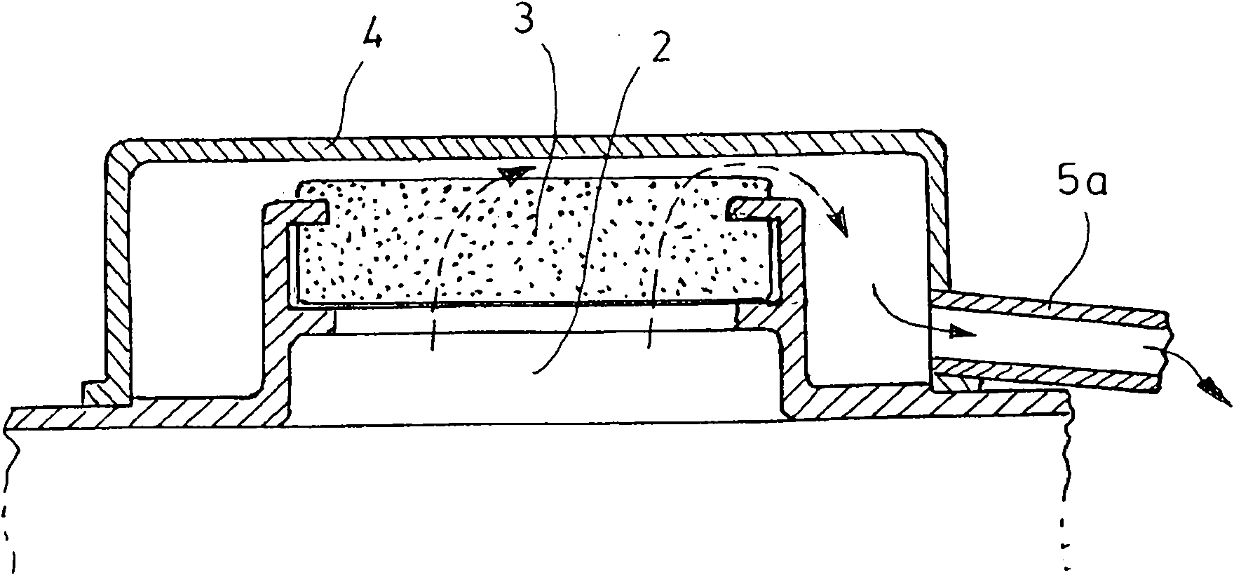
[0019] As this can be particularly drawn from the drawings, a central air inlet and outlet opening 2 is provided on the upper side of the reducing agent container 1 in the in...


PUM


Abstract

The invention relates to a reducing agent tank for holding a liquid reducing agent as a so-called SCR tank. The SCR tank comprises at least one device for deaerating the tank, which device is closed off by means of at least one pressure-compensating element which permits an exchange of gas but which closes off the tank in a liquid-tight manner. The reducing agent tank also comprises at least one deaeration line which communicates with the pressure-compensating element, with the deaeration line being guided at least to a point above the maximum permissible fording level of the tank when the tank is in the installation position. The deaeration line has at least one first downward-sloping line section which branches into a second rising line section for deaeration and a third falling line section for gravity-induced condensate drainage.

Description

Technical field [0001] The invention relates to a working fluid container for a motor vehicle, in particular a reducing agent container for containing a liquid reducing agent for catalytic denitrification of exhaust gas. The so-called SCR method is often used in the exhaust gas purification of diesel vehicles, mainly in commercial vehicles. SCR refers to selective catalytic reduction, in which nitrogen oxides are reduced with ammonia. The required ammonia is injected into the exhaust gas path upstream of the SCR catalyst, for example in the form of an aqueous urea solution. Ammonia and carbon dioxide are produced from the urea aqueous solution through the hydrolysis reaction. Ammonia can react with nitrogen oxides in the exhaust gas at a corresponding temperature in the catalytic converter. Background technique [0002] A reducing agent container for urea present in an aqueous solution is usually provided in the vehicle concerned. Urea releases ammonia, which can cause uncomf...

Claims


Application Information

Patent Timeline
Patent Type & Authority Patents(China)
IPC IPC(8): F01N3/20B60K15/035
CPCF01N2610/1413Y02T10/24F01N2610/02F01N2610/1466F01N3/2066F01N2610/1406Y02T10/12Y10T137/3021Y10T137/3093Y10T137/6881Y10T137/86324Y02A50/20B60K15/035F01N3/20
Inventor R·科尔贝格J·马格洛夫斯基R·施韦尔V·特洛伊特
Owner KAUTEX TEXTRON
Why Eureka
Try Eureka