Method and device for the angle sensor-free position detection of the rotor shaft of a permanently excited synchronous machine based on current signals and voltage signals

A synchronous motor and rotor shaft technology, applied in motor generator control, control of electromechanical transmissions, electric/electrical converters, etc., can solve problems such as inaccurate rotor angles, insufficient machine models, etc., and achieve real-time calculation and high precision. Effect

Inactive Publication Date: 2012-02-01
ROBERT BOSCH GMBH
View PDF7 Cites 8 Cited by
  • Summary
  • Abstract
  • Description
  • Claims
  • Application Information

AI Technical Summary

Problems solved by technology

[0005] However, these known methods have the disadvantage that they either have additional sensors for determining the

Method used


Image

  • Method and device for the angle sensor-free position detection of the rotor shaft of a permanently excited synchronous machine based on current signals and voltage signals
  • Method and device for the angle sensor-free position detection of the rotor shaft of a permanently excited synchronous machine based on current signals and voltage signals
  • Method and device for the angle sensor-free position detection of the rotor shaft of a permanently excited synchronous machine based on current signals and voltage signals

Examples


Embodiment Construction

[0070] exist figure 1 The schematic structure of the dq fundamental model with input / output transformation is shown in . Motor input or machine voltage U in the αβ coordinate system fixed relative to the stator or relative to the location αβ 14 through the rotation matrix T ( ) 11 is transformed into the input signal U in the dq coordinate system fixed relative to the rotor dq .

[0071] The transformed input signal U dq is input to the machine model ∑ dq 12 in. Machine model∑ dq 12 as output with the estimated rotation angle (position) 16 and machine current I dq . Machine current I fixed relative to the rotor dq By inverse rotation matrix T -1 ( ) 13 is converted back to the fixed machine current I relative to the stator αβ 15, which is converted back to the output quantity. rotation angle 16 is fed here to the rotation matrix T ( )11 and the inverse rotation matrix T -1 ( ) 13, where applicable:

[0072] and .

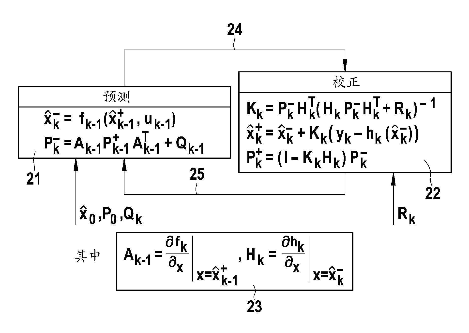
[0073] figure 2 The predictor...


PUM


Abstract

The present invention relates to a device and to a method for determining position information of the rotor shaft of an electric machine on the basis of at least one input signal received by the electric machine, wherein the received input signal is supplied to a model of the electric machine. The position information of the rotor shaft is determined by means of the model based on the supplied input signal, wherein the model represents non-linear saturation effects of the electric machine. The model of the electric machine is an expanded Kalman filter in which the non-linear saturation effects of the electric machine are described by a polynomial.

Description

technical field [0001] The invention relates to a method and equipment for detecting the position of a rotor shaft of a permanent magnet synchronous motor in a manner without an angle sensor based on a current signal or a voltage signal. Background technique [0002] Synchronous motors are currently used in a variety of different sizes and power levels, since synchronous motors are superior to asynchronous motors and DC motors in many applications due to their lower wear and constant speed of rotation. However, in order to be able to drive a permanent magnet synchronous motor at a variable number of revolutions, the magnetic field must rotate synchronously with the rotor of the motor. For synchronization, the position of the rotor shaft, the so-called rotor angle, must be known and a constant rotating magnetic field must be generated. [0003] A method and a device for position detection of a rotor shaft of a permanent magnet synchronous machine are known from DE 10 2007 05...

Claims


Application Information

Patent Timeline
IPC IPC(8): H02P23/12H02P21/00G05B13/04
CPCA63B21/0004G05B17/02G05B13/048H02P1/00H02P21/13H02P21/0039H02P23/12H02P21/24
Inventor U.福尔默M.比策尔
Owner ROBERT BOSCH GMBH
Why Eureka
Try Eureka