
High-efficiency combined water purifier

A water purifier and high-efficiency technology, applied in the field of water treatment, can solve the problems of high energy consumption of pump stations, heavy maintenance workload, and large head loss of pipelines, etc., to achieve expanded filtration area, small footprint, and short water production time short effect

Inactive Publication Date: 2012-02-08
上海安鼎济水处理科技有限公司
View PDF5 Cites 2 Cited by
  • Summary
  • Abstract
  • Description
  • Claims
  • Application Information

AI Technical Summary

Problems solved by technology

[0002] Although large-scale urban water plants provide high-quality living and production water for cities and villages through dense underground pipelines, there are still many problems in their huge water distribution systems: (1) The long distance and large diameter of pipelines lead to investment Very expensive; (2) The head loss of the pipeline is large, the energy consumption of the pumping station is high, and the daily operation cost is increased; (3) Problems such as leakage of the pipeline network, bursting of the pipe, and water cutoff cause many safety hazards and a large maintenance workload; (4) ) The secondary pollution of the pipeline is serious, which makes it difficult to guarantee the water quality, and at the same time increases the dosage of disinfectant

Method used


Image

  • High-efficiency combined water purifier
  • High-efficiency combined water purifier
  • High-efficiency combined water purifier

Examples


Embodiment 1

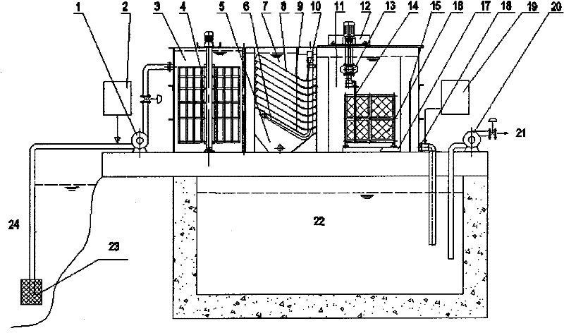
[0045] like figure 1 As shown, the device consists of water inlet pump 1, coagulant dosing device 2, reaction tank 3, grid variable hole stirring paddle 4, sludge bucket 5, forced outlet pipe 6, sedimentation tank 7, co-current swash plate 8. Sedimentation water collector 9, clean water outlet hose 10, filter tank 11, dredging truck 12, dredging pump 13, dredging pipe 14, water outlet weir 15, blanket filter 16, water collecting trunk 17, Clean water outlet 18, disinfectant dosing device 19, clean water lifting pump 20, user water 21, clean water pool 22, water intake 23 and river course 24 are formed. The reaction tank 3 mainly carries out the coagulation process. The raw water is drawn by the water inlet pump 1, and the raw water and the chemical agent are fully mixed and stirred, and then enters the sedimentation tank 7, and the sedimentation tank 7 carries out preliminary precipitation, and most of the settled sludge is discharged from the bottom of the sedimentation tank...


PUM


Abstract

The invention belongs to the technical field of water treatment, and particularly relates to a high-efficiency combined water purifier. The water purifier comprises a reaction tank, a precipitation tank and a filtration tank, wherein one end of a water inlet pump is connected to one side of the upper part of the reaction tank through a pipeline and a valve; grid variable-orifice stirring blades are arranged in the reaction tank; the bottom of the precipitation tank is provided with a forcible water outlet pipe, and the middle part of the precipitation tank is provided with a co-current oblique plate; the bottom of the co-current oblique plate is provided with a precipitation water collector; the precipitation water collector is connected with a pure water outlet hose; the top of the filtration tank is provided with a dredge traveling crane, a vertical blanket-shaped filter disc and a water outlet weir are arranged in the filtration tank, the bottom of the filtration tank is provided with a water collection trunk passage, a pure water outlet is formed on one side of the bottom of the filtration tank, and the dredge traveling crane can move back and forth on the top of the filtration tank.; a dredge pump is fixed below the dredge traveling crane; and one end of a dredge pipe is connected with the dredge pump, and the other end of the dredge pipe is positioned on one side of the blanket-shaped filter disc. The water purifier has the advantages of compact structure, small floor area, shallow tanks, stable water quality, easiness and convenience in management and capability of keeping capacity retention time of the pure water be only about several minutes, and fully shows the characteristic of high efficiency compared with the conventional flow.

Description

technical field [0001] The invention belongs to the technical field of water treatment, and in particular relates to a high-efficiency combined water purifier. Background technique [0002] Although large-scale urban water plants provide high-quality living and production water for cities and villages through dense underground pipelines, there are still many problems in their huge water distribution systems: (1) The long distance and large diameter of pipelines lead to investment Very expensive; (2) The head loss of the pipeline is large, the energy consumption of the pumping station is high, and the daily operation cost is increased; (3) Problems such as leakage of the pipeline network, bursting of the pipe, and water cutoff cause many safety hazards and a large maintenance workload; (4) ) The secondary pollution of the pipeline is serious, which makes it difficult to guarantee the water quality, and at the same time increases the dosage of disinfectant. [0003] Therefore...

Claims


Application Information

Patent Timeline
IPC IPC(8): B01D36/04
Inventor 张亚雷陈翼孙黄维黄永宽张合平龚本涛沈峥
Owner 上海安鼎济水处理科技有限公司
Learn More