Method for capturing specific laser processing beam spot through projection imaging

A laser processing and projection technology, applied in laser welding equipment, metal processing equipment, manufacturing tools, etc., can solve problems such as control uncertainty, and achieve the effect of suppressing uncertainty and sharpening the edge of the beam spot

Inactive Publication Date: 2012-02-08
TSINGHUA UNIV
View PDF4 Cites 1 Cited by
  • Summary
  • Abstract
  • Description
  • Claims
  • Application Information

AI Technical Summary

Problems solved by technology

[0006] Due to the diffraction effect, there is always extra diffracted light at the sides and corners of the beam spot with a specific shape, and this part of the diffracted light will also affect the substrate chip, thus bringing uncertainty in control

Method used


Image

  • Method for capturing specific laser processing beam spot through projection imaging
  • Method for capturing specific laser processing beam spot through projection imaging

Examples


Embodiment Construction

[0015] The object of the present invention is to provide a method for obtaining a specific laser processing beam spot by means of projection imaging. The present invention adopts a projection imaging system to realize the beam shaping process, in addition to obtaining the desired shape of the beam spot, it can also suppress the diffraction part at the edge of the beam spot and obtain the sharp edge of the beam spot. The composition of the projection imaging system is as follows:

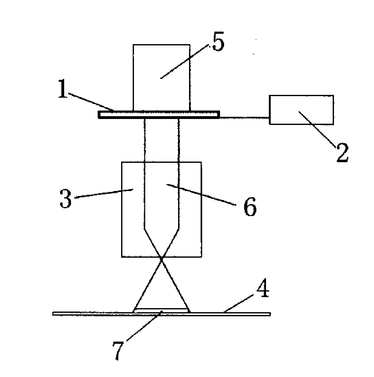
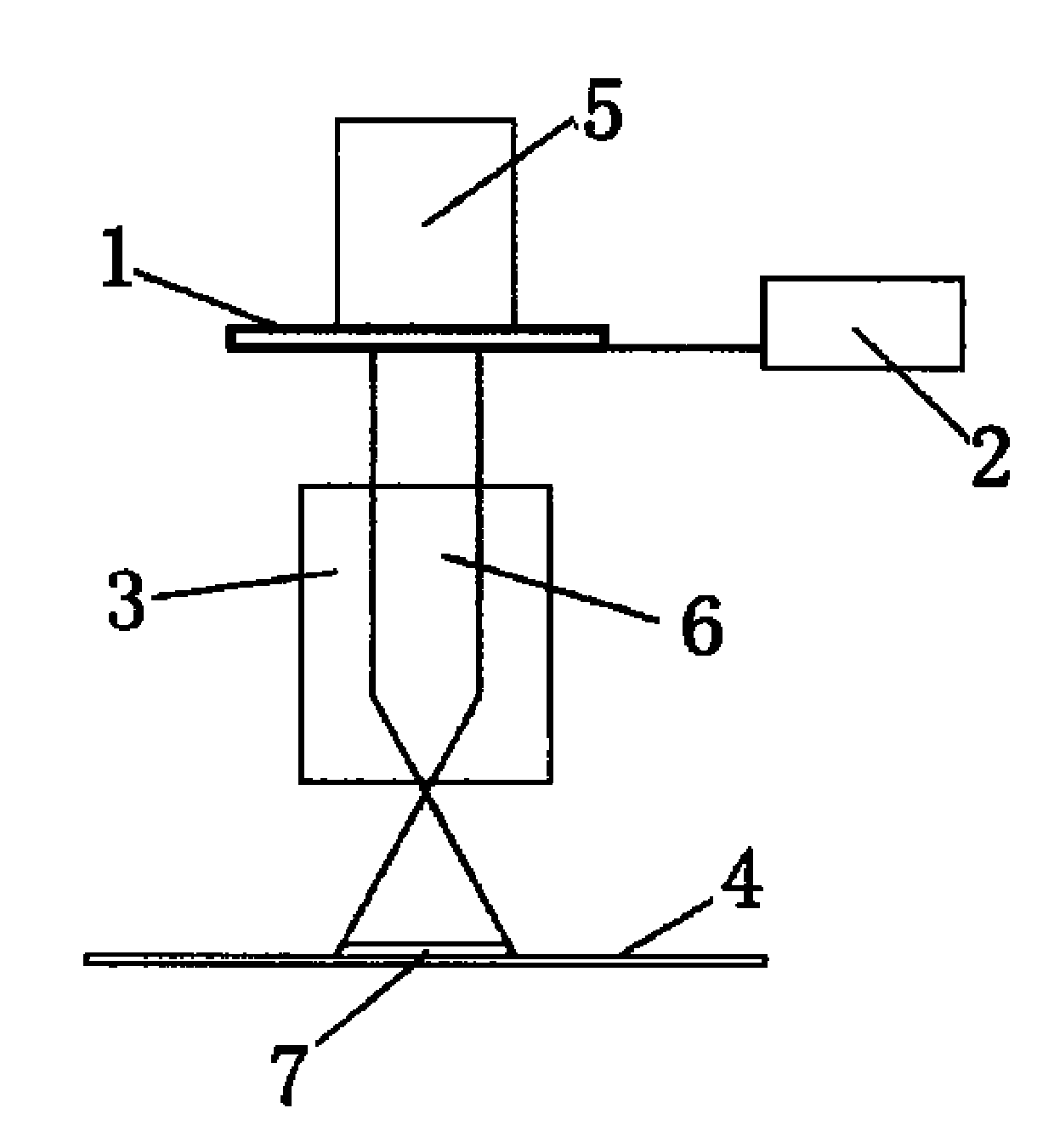
[0016] The projection imaging system generally consists of three parts, one is the object, the other is the imaging lens group, and the third is the screen and image. The composition of the projection imaging system is as follows: figure 1 shown.

[0017] Among the figure, design a series of light-transmitting figures on the photolithography plate 1 (mainly adopt the figures with middle width, upwards or downwards gradually reducing to zero in geometric shape, such as trapezoid or regular polygon; ...


PUM


Abstract

The invention discloses a method for capturing a special laser processing beam spot through projection imaging, belonging to the scope of semi-conductor manufacturing equipment. A series of transmitting graphics are designed on a photolithography mask, and the photolithography mask is moved through a driving mechanism so as to select a specific transmitting graphic on the photolithography mask. The incident laser beams pass through the specific transmitting graphic on the photolithography mask, then enter a projection imaging lens group and are projected and form an image on the surface of a wafer, forming a desired lasing beam spot. With sharp edges, the beam spot sufficiently restrains the uncertainty of process control in laser processing caused by the diffraction effect. On the other hand, since the series of transmitting graphics can be put on the photolithography mask and the ratio of the projection photolithographic system can be designed to be variable, the geometric shape and the size of the laser beam spot obtained through the method are freely adjustable. Therefore, the method can ensure to obtain ideal and evener process control effect in laser processing.

Description

technical field [0001] The invention belongs to the scope of semiconductor manufacturing equipment, in particular to a method for acquiring a specific laser processing beam spot by using projection imaging. Background technique [0002] Laser processing is used in integrated circuits and related manufacturing fields, and its specific applications include laser annealing, laser recrystallization, laser-assisted thin film deposition, etc. [0003] Due to the limitation of the laser beam spot size, if the entire surface of a wafer with a larger size is to be processed, it is necessary to form a relative movement between the laser beam and the wafer, so that as the processing time goes by, the laser beam The spot will move and cover the entire wafer surface. For any laser processing using laser scanning or step scanning, etc., the main requirement is that there are no gaps or overlaps between two consecutive scanning lines. If the above situation occurs, there will be areas on...

Claims


Application Information

Patent Timeline
Patent Type & Authority Applications(China)
IPC IPC(8): B23K26/073
Inventor 严利人周卫刘朋窦维治刘志弘
Owner TSINGHUA UNIV
Why Eureka
Try Eureka