Non-rotary sinking roller for hot-dip galvanization

A sinking roll and hot-dip galvanizing technology, which is applied in hot-dip galvanizing process, coating, metal material coating process, etc., can solve the problem of not fully considering the dynamic changes of the incoming steel strip, the inability to significantly increase the running speed of the steel strip, and the use of Narrow occasions and other issues, to achieve the effect of eliminating contact friction, improving surface quality, and improving overall productivity

Inactive Publication Date: 2013-01-02
BAOSHAN IRON & STEEL CO LTD
View PDF5 Cites 0 Cited by
  • Summary
  • Abstract
  • Description
  • Claims
  • Application Information

AI Technical Summary

Problems solved by technology

However, the application occasions of this method are very narrow, and the dynamic changes of the specification parameters such as the thickness, width and tension of the incoming steel strip are not fully considered. It is not feasible to use a uniform and fixed lead core weight to balance the changing incoming steel strip. It may even have negative effects; in addition, Japanese Patent JP11246955A makes a through hole inside the sinking roller, fixes a support cylinder between the two support arms, and swayes the hollow sinking roller in the horizontally placed cylinder, sinking The large-area friction fit between the inner surface of the roller and the cylinder replaces the original small-area fit between the shaft head and the bearing bush at both ends to improve the service cycle of the sinking roller once it goes online. This technical solution fails to fundamentally solve the wear and tear. problem, also due to the low coaxial precision at both ends, the running speed of the steel belt cannot be significantly increased

Method used


Image

  • Non-rotary sinking roller for hot-dip galvanization
  • Non-rotary sinking roller for hot-dip galvanization
  • Non-rotary sinking roller for hot-dip galvanization

Examples


Embodiment 1

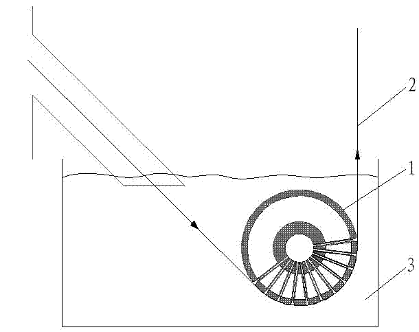
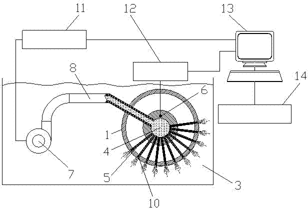
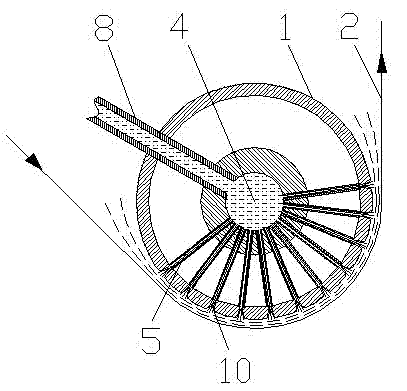
[0016] Such as figure 1 , 2 , 3, and 4, a non-rotating hot-dip galvanized sinking roll, including a fixed sinking roll body 1, an ultra-high temperature pressure gauge 6, a high-temperature zinc pump 7, a guide tube 8, a zinc pump control system 11, a pressure signal The acquisition system 12 and the automatic control system 13, the fixed sinking roller body 1 is fixed and suspended in the zinc pool 3 through the support arms 9 at both ends; the outer surface of the fixed sinking roller body 1 is provided with a matrix of injection ports 10, so The spray port matrix 10 is composed of several spray port arrangements, and the area covered by the spray ports corresponds to the steel strip 2. In this embodiment, the spray angle range of the spray port matrix 10 enters the zinc pool according to the steel strip 2 at the exit of the continuous annealing furnace. The inclination angle at 3 o'clock and the angle between the time when the steel strip 2 leaves the zinc pool 3 are set t...


PUM


Abstract

The invention relates to the field of steel strip hot-dip galvanization, and especially relates to a sinking roller for hot-dip galvanization. A non-rotary sinking roller for hot dip galvanization is characterized in that: the axis of a fixed sinking roller body is provided with a mixing chamber; the outer surface of the fixed sinking roller body is provided with a jet orifice matrix, and an areacovered by the jet orifice matrix corresponds with a steel strip; the mixing chamber is communicated with each jet orifice of the jet orifice matrix through a jet tube; two ends of the mixing chamberare respectively connected with a high temperature zinc pump through a honeycomb duct; the output terminal of an ultrahigh temperature pressure meter is connected with the input terminus of an automatic control system through a pressure signal acquisition system; the output terminal of a zinc pump control system has a control connection with the high temperature zinc pump; and the input terminus of the zinc pump control system is connected with the output terminal of the automatic control system. Contact friction force between the steel strip and the surface of the fixed sinking roller body is eliminated in the invention, so a problem of the frequent replacement of the sinking roller caused by wearing is avoided, thereby the whole production power of a production line is improved and the labor intensity of operators is reduced.

Description

technical field [0001] The invention relates to the field of hot-dip galvanizing for steel strips, in particular to a hot-dip galvanizing sinking roll. Background technique [0002] In the current continuous hot-dip galvanizing / aluminum-zinc production line, in order to ensure that the depth and time of immersion of the steel strip in the continuous annealing furnace into the liquid zinc pool meet the production requirements, and based on the consideration of production costs, driven sinking rollers are generally used to achieve The steering of the steel belt ensures sufficient tension. [0003] The sinking roll for hot-dip galvanizing is a driven hollow roll. After the steel strip comes out of the furnace mouth, it bypasses the surface of the roll body and then exits the zinc pool. At this time, the steel strip forms a certain pressure and friction with the surface of the sinking roll under a certain tension. , causing the supporting frames at both ends of the sinking roll...

Claims


Application Information

Patent Timeline
Patent Type & Authority Patents(China)
IPC IPC(8): C23C2/06C23C2/40
Inventor 段明南王健
Owner BAOSHAN IRON & STEEL CO LTD
Why Eureka
Try Eureka