
Turbine vane with dusting hole at the base of the blade

A technology of turbine blades and dust removal holes, applied in the direction of blade support elements, machines/engines, stators, etc., can solve problems such as damage to the cavity, increase in cavity size, etc.

Active Publication Date: 2012-02-08
SN DETUDE & DE CONSTR DE MOTEURS DAVIATION S N E C M A
View PDF4 Cites 4 Cited by
  • Summary
  • Abstract
  • Description
  • Claims
  • Application Information

AI Technical Summary

Problems solved by technology

Installing trailing edge cavity dust vents on blades with short chords may cause an abnormal increase in the size of this cavity, but at the same time damage other cavities

Method used


Image

  • Turbine vane with dusting hole at the base of the blade
  • Turbine vane with dusting hole at the base of the blade
  • Turbine vane with dusting hole at the base of the blade

Examples


Embodiment Construction

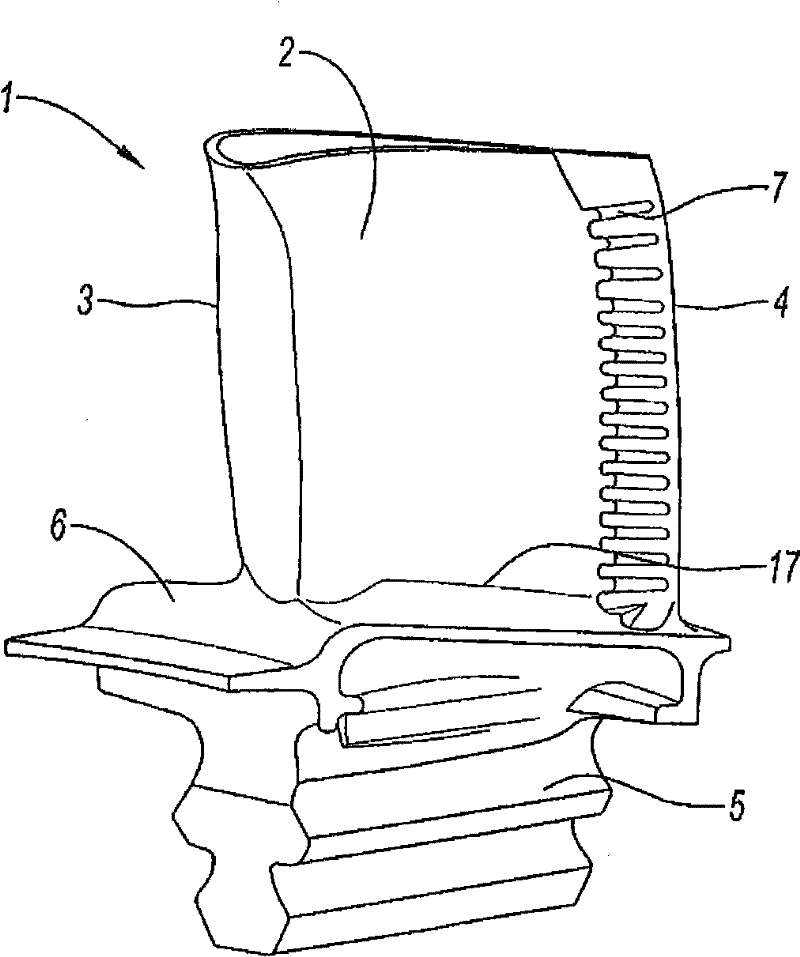
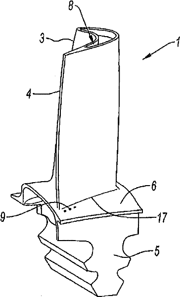
[0030] Referring to Figure 1, there is shown a high pressure turbine blade 1 comprising a blade 2 extending between a leading edge 3 and a trailing edge 4, mounted on a platform 6 supported by a blade root 5; the platform 6 is defined by a circular transition The radius 17 is connected to the blade 2 . The blade 1 is provided with a number of ventilation holes 7 at its trailing edge 4 for discharging the cooling air circulating in the cavity of the trailing edge. Figure 2 shows the location of the prior art tunnel 8 which can function as a trailing edge cavity dust removal hole; the hole 8 is at the top of the blade at this cavity. The blade 1 also includes holes 9 on the platform 6 on the suction side of the blade 2. The air from the blade root 5 flows through these holes. The tunnel 9 shown in Figure 2 is located at the trailing edge 4, and its air comes from the fresh air supply duct of the trailing edge cavity.

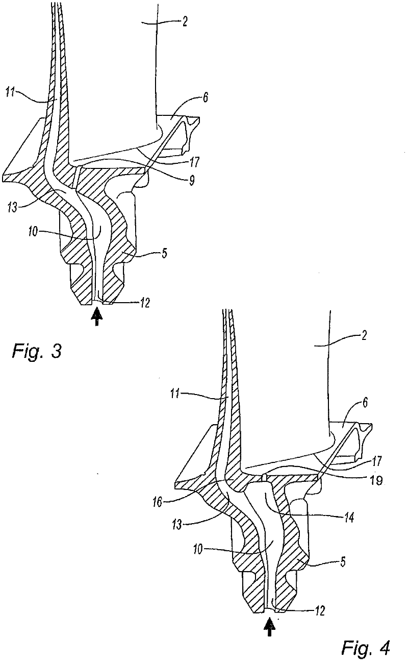
[0031] FIGS. 3 and 4 each show a cross-section of a turbin...


PUM


Abstract

The invention relates to a cooled turbine vane for a turbine engine, that comprises a blade (2) mounted on a platform (6) carried by a base (5), said blade having one or more cavities formed therein for cooling air circulation, the cavity (11) extending along the trailing edge and being supplied with cooling air by a supply duct (10) connecting an air intake (12) located in the lower portion of the base (5) and the cavity (11) of the trailing edge by defining a bend (13) within said base, characterised in that the duct (10) comprises, on an axis substantially radial relative to the air intake (12) a bell-shaped niche (14) located under the platform (6), said niche being open at the top thereof via a dusting hole (19) extending through the platform and being defined at the foot of the base (5) by walls extending substantially radially from the platform (6) in order to close it laterally.

Description

technical field [0001] The field of the invention is the field of turbomachines and in particular the field of cooling the turbine vanes of these turbomachines. Background technique [0002] Modern turbines are usually produced in an integrated form of component assembly. First, they consist of one or more compressor assemblies arranged in series that compress the intake air to the intake. Then, the air enters the combustion chamber to mix with fuel and burn. Combustion gases flow through one or more turbine assemblies that drive the compressor. Finally, the gas is either discharged to the jet nozzle for propulsion power, or to a free turbine for power transmission via the drive shaft. [0003] These modern turbines require cooling due to the high temperature of the gas leaving the combustion chamber, which means that fresh air ventilation lines are installed to cool the metal of the turbine blades when the turbine is operating. Ventilation air is drawn from the outside ...

Claims


Application Information

Patent Timeline
Patent Type & Authority Applications(China)
IPC IPC(8): F01D5/14F01D5/18F01D9/02
CPCF01D5/14F01D5/143F01D5/18F01D5/186F01D5/187F01D9/02F05D2240/80F05D2240/81F05D2260/202F05D2260/607Y02T50/60
Inventor 瑟奇·路易斯·安图尼斯瑟奇·路易斯·鲍瑞帕特里斯·吉恩-马克·罗赛特
Owner SN DETUDE & DE CONSTR DE MOTEURS DAVIATION S N E C M A
Learn More