
Quenching method of wind power bearing gear ring

A ring gear and bearing technology, which is applied in the field of quenching of wind power bearing ring gear, can solve the problems of shortening the service life of bearings, accidents, product scrapping, etc., and achieve the effect of ensuring hardness and preventing deformation

Inactive Publication Date: 2012-02-15
LUOYANG LYC BEARING
View PDF4 Cites 10 Cited by
  • Summary
  • Abstract
  • Description
  • Claims
  • Application Information

AI Technical Summary

Problems solved by technology

Using the indexing method of traditional technology, it is easy to anneal the previous quenched tooth surface during quenching, which will reduce the hardness of the quenched tooth surface, resulting in unqualified hardness of the tooth surface of the entire ring gear. Facial fracture, major accident
In addition, the traditional tooth surface quenching process does not quench at intervals, which easily deforms the ring gear, prolongs the production cycle and even makes the product scrapped; using the traditional tooth surface quenching process, it is easy to cause uneven temperature on the tooth surfaces on both sides of the tooth groove, and the cooling cannot be done at the same time. , causing cracks on the tooth surface and tooth root, and once the gear cracks, it is usually irreparable, causing the entire product to be scrapped due to this process

Method used


Image

  • Quenching method of wind power bearing gear ring
  • Quenching method of wind power bearing gear ring
  • Quenching method of wind power bearing gear ring

Examples


Embodiment 1

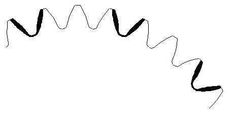
[0014] Embodiment 1: Use profiling inductors to carry out quenching and heating along the tooth grooves of the ring gear, and the heating and cooling adopt a synchronous method, that is, the induction heater moves from top to bottom along the tooth grooves for induction heating, and simultaneously heats the adjacent The tooth surface of the tooth is sprayed and cooled synchronously; figure 1 As shown, the method of quenching every other tooth is adopted; the part rotates once, that is, the 60 teeth of the ring gear are a working cycle, and the 60 teeth of the ring gear are divided into two groups, the first group is the 1st, 3rd, and 3rd. 5, 7...59 teeth, the second group is the 2nd, 4, 6, 8...60 teeth. In the first working cycle, the 30 teeth of the first group are induction hardened sequentially along the tooth grooves, and in the second working cycle, the 30 teeth of the second group are induction hardened sequentially along the tooth grooves. Finished induction hardening ...

Embodiment 2

[0016] Embodiment 2: Use profiling inductors to perform quenching and heating along the tooth grooves of the ring gear, and the heating and tooth back cooling adopt a synchronous method, that is, the inductor moves from top to bottom along the tooth grooves for induction heating, and the adjacent The tooth surface of the tooth is subjected to synchronous spray cooling. Such as figure 2 As shown, the method of quenching every two teeth is adopted, and the part rotates once, that is, the 60 teeth of the ring gear are one working cycle, and the 60 teeth of the ring gear are divided into three groups, the first group is the 1st and 4th , 7, 10, ... 58 teeth, the second group is the 2nd, 5, 8, 11, ... 59 teeth, and the third group is the 3rd, 6, 9, 12, ... 60 teeth. In the first working cycle, induction hardening is carried out on the 20 teeth of the first group along the tooth groove in sequence; in the second working cycle, induction hardening is carried out on the 20 teeth of ...


PUM


Abstract

The invention relates to a quenching method of a wind power bearing gear ring, which belongs to the field of heat treatment process. A profile induction heater carries out quenching heat treatment along a tooth groove of the gear ring, and the heating and the gear back cooling are synchronously carried out. The quenching method is characterized in that a tooth interval quenching method is adopted, teeth of the gear ring are divided into a plurality of groups according to the preset quenching intervals, the interval grouping quantity is S1+1, the work circulation times of the inductor are the same as the grouping number of the teeth on the gear ring, during the heating, both sides of the inductor are connected with cooling water pipes, the tooth surfaces of the teeth adjacent to the heated teeth are synchronously cooled, and the effective deformation control and the hardness control are realized. The quenching method has the advantages that the tooth interval quenching mode is adopted on the gear ring, front and back quenching tooth surfaces are not mutually influenced, and the primary quenched tooth surface is ensured not to be annealed, so the hardness is ensured; and during the thin-wall gear ring quenching, a multi-tooth interval quenching method can be adopted, and the deformation can be effectively prevented.

Description

technical field [0001] The invention belongs to the field of heat treatment technology, and mainly relates to a quenching method for a ring gear of a wind power bearing. Background technique [0002] Quenching of wind power bearing ring gear is prone to two major problems: deformation and cracks. Using the indexing method of traditional technology, it is easy to anneal the previous quenched tooth surface during quenching, which will reduce the hardness of the quenched tooth surface, resulting in unqualified hardness of the tooth surface of the entire ring gear. The surface fractured and a major accident occurred. In addition, the traditional tooth surface quenching process does not quench at intervals, which easily deforms the ring gear, prolongs the production cycle and even makes the product scrapped; using the traditional tooth surface quenching process, it is easy to cause uneven temperature on the tooth surfaces on both sides of the tooth groove, and the cooling cannot...

Claims


Application Information

Patent Timeline
Patent Type & Authority Applications(China)
IPC IPC(8): C21D1/10C21D9/32
CPCY02P10/25
Inventor 霍晓磊姚义峰林国福李崇崇冯占彪王磊赵向明李国振
Owner LUOYANG LYC BEARING
Learn More