Gas burner capable of adjusting premix

A gas burner and premixing technology, which is applied to gas fuel burners, burners, combustion methods, etc., can solve the problems of unstable gas volume, inability to meet the requirements of the process curve, and difficult process control.

Inactive Publication Date: 2012-02-15
金艺
View PDF5 Cites 9 Cited by
  • Summary
  • Abstract
  • Description
  • Claims
  • Application Information

AI Technical Summary

Problems solved by technology

In actual operation, due to the influence of gas pressure, the amount of gas injected by the burner is extremely unstable, small and large, and the gas injection volume is small, which cannot meet the requirements of the process curve, the process is difficult to control, the combustion efficiency is not good, an

Method used


Image

  • Gas burner capable of adjusting premix
  • Gas burner capable of adjusting premix

Examples


Example Embodiment

[0008] 5. Specific implementation mode: The present invention will be further described below in conjunction with the drawings:

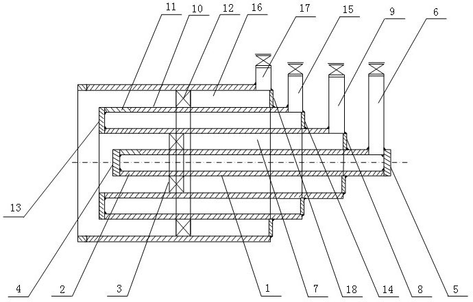
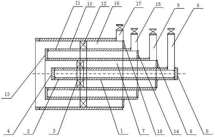
[0009] The small nozzle gas pipe 1 of the gas burner is designed according to the minimum heat required to implement the furnace. The small nozzle gas pipe 1 is located in the center of the gas burner, and the annular space between the small nozzle gas pipe 1 and the large nozzle gas pipe 10 is an air passage 7. The front side of the small nozzle gas pipe 1 has gas injection holes 2 circumferentially, the front end is welded with a blocking plate 4, the rear end is welded with a blocking plate 5, and the rear side is connected with gas through a gas inlet pipe 6 welded to it. The gas inlet pipe 6 is equipped with a gas control valve for adjusting and controlling the amount of gas entering the small nozzle gas pipe 1. The air swirl fin 3 is set on the outside of the small nozzle gas pipe 1. The height of the air swirl fin 3 is slightly smaller than the...

Example Embodiment

[0013] Example 1:

[0014] The invention is used in the old factory No. 1 kiln of Puyang City Punai Functional Materials Co., Ltd. The furnace is 1.6 million kcal, the pressure of natural gas is 8 Pa, and one furnace is equipped with 8 burners. Calculate according to the furnace type, the heat required by the furnace, and the natural gas pressure, and distribute the natural gas amount to the small nozzle gas pipe 1 and the large nozzle gas pipe 10 in the eight burners. The small nozzle gas pipe 1 sprays the natural gas volume of 0.5-5 m3 / h, and the large nozzle gas pipe 10 sprays the natural gas volume of 5-25 m3 / h, and then ignites on the small nozzle gas pipe 1 after processing and assembly. According to the heating curve, the temperature will be increased from 100℃ to 400℃, and after a constant temperature of 400℃ for 8 hours, switch to the large nozzle gas pipe 10. According to the heating curve 500-600-700-800-900-1100℃, the temperature will be increased slowly to 1100℃, and...

Example Embodiment

[0015] Example 2:

[0016] The furnace used in Puyang Glass Factory is 1.6 million kcal, one burner, and the natural gas pressure is 0.2Mpa. It is designed, processed, installed, fired and operated according to the furnace type and the heat required by the furnace. The natural gas injection volume per hour is 187 m3 / h. The original natural gas injection rate is 200 m3 / h, saving 7%.


PUM


Abstract

The invention relates to a gas burner capable of adjusting premix, and the gas burner is provided with a small nozzle gas pipe and a large nozzle gas pipe, wherein the small nozzle gas pipe is located in the center of the burner; the large nozzle gas pipe is sleeved at the outer side of the small nozzle gas center; air passages are respectively arranged between the small nozzle gas pipe and the large nozzle gas pipe and between the large nozzle gas pipe and the outer wall of the burner; gas orifices are respectively arranged at the front end faces of the small nozzle gas pipe and the large nozzle gas pipe; the front and rear ends of the small nozzle gas pipe and the large nozzle gas pipe are respectively provided with a baffle, the rear ends of the small nozzle gas pipe and the large nozzle gas pipe are communicated with gas through a gas inlet pipe and a gas control valve; and the air passages are respectively internally provided with an air swirl plate and the rear ends of the air passages are respectively provided with a baffle, the rear ends of the air passages are communicated with compressed air through the air inlet pipe and the air control valve. Gas quantity and combustion air rate ejected by the burner are both adjustable, and the gas burner has the advantages of fast burning velocity, high flame temperature, improved heat efficiency, decreased gas volume and low cost.

Description

technical field [0001] The invention relates to a burner, in particular to a gas burner with adjustable premixing for natural gas, gas gas, coal gas and biogas. Background technique [0002] Power plant boilers, various industrial boilers, civil heating boilers, various heating furnaces, various light industrial kilns, and steelmaking furnaces all need burners, which usually use natural gas, gas, coal gas or biogas as fuel. When working, it is necessary to have a strict heating curve to protect the furnace body and ensure the product quality in the furnace. The nozzles of the currently used gas burners are designed according to the maximum amount of gas entering, and there is only one specification. In actual operation, due to the influence of gas pressure, the amount of gas injected by the burner is extremely unstable, small and large, and the gas injection volume is small, which cannot meet the requirements of the process curve, the process is difficult to control, the co...

Claims


Application Information

Patent Timeline
IPC IPC(8): F23D14/02F23D14/60F23D14/62
Inventor 金艺金春花王芳金术杰姜宇金盛珠
Owner 金艺
Why Eureka
Try Eureka