Micro angular swing control reflecting mirror followed by flexible auxiliary arm with superhigh angular sensitivity and high frequency response

A technology of auxiliary arms and mirrors, which is applied in the direction of optical components, optics, instruments, etc., can solve the problems of complex device manufacturing process, increase of liquid micro-wedge prism, increase of electrode plate voltage difference, etc., to ensure fast dynamic tracking response ability Effect

Inactive Publication Date: 2012-02-15
HARBIN INST OF TECH
View PDF5 Cites 8 Cited by
  • Summary
  • Abstract
  • Description
  • Claims
  • Application Information

AI Technical Summary

Problems solved by technology

In this method, the maximum deflection angle of the beam is related to the refractive index of the liquid material used. The realized beam deflection range can reach 30°, and the response speed is on the order of milliseconds. loss, the voltage between the electrode plates on both sides of the cavity wall needs to reach tens of volts, and in order to increase the beam deflection angle, it is necessary to increase the voltage difference between the electrode plates to increase the wedge angle of the liquid micro-wedge prism, while The distance between the electrode plates is on the order of microns to millimeters, so a very strong electric field is formed in the cavity, which is easy to cause breakdown, and the manufacturing process of the device is relatively complicated

Method used


Image

  • Micro angular swing control reflecting mirror followed by flexible auxiliary arm with superhigh angular sensitivity and high frequency response
  • Micro angular swing control reflecting mirror followed by flexible auxiliary arm with superhigh angular sensitivity and high frequency response
  • Micro angular swing control reflecting mirror followed by flexible auxiliary arm with superhigh angular sensitivity and high frequency response

Examples


Embodiment Construction

[0025] Specific embodiments of the present invention will be described in detail below in conjunction with the accompanying drawings.

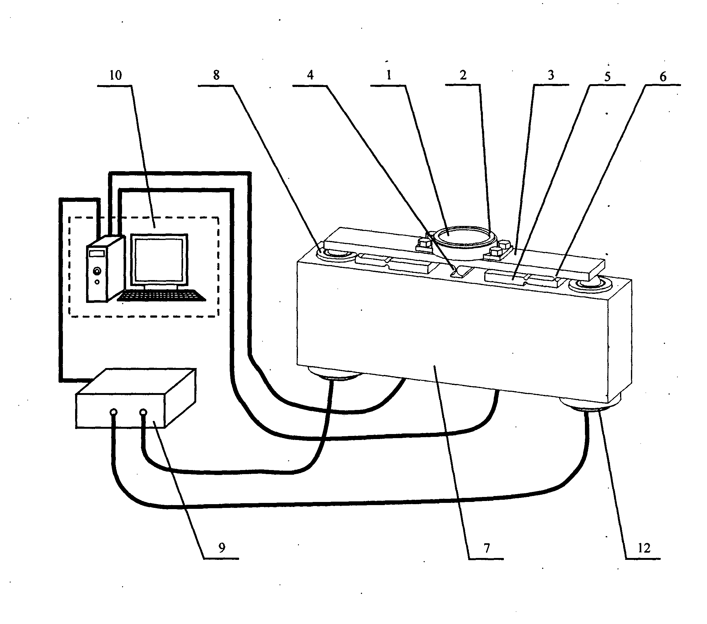
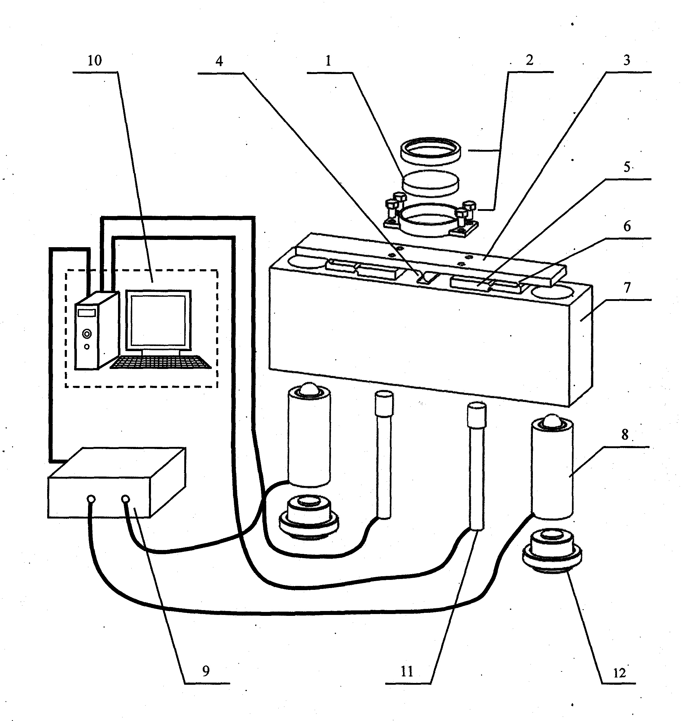
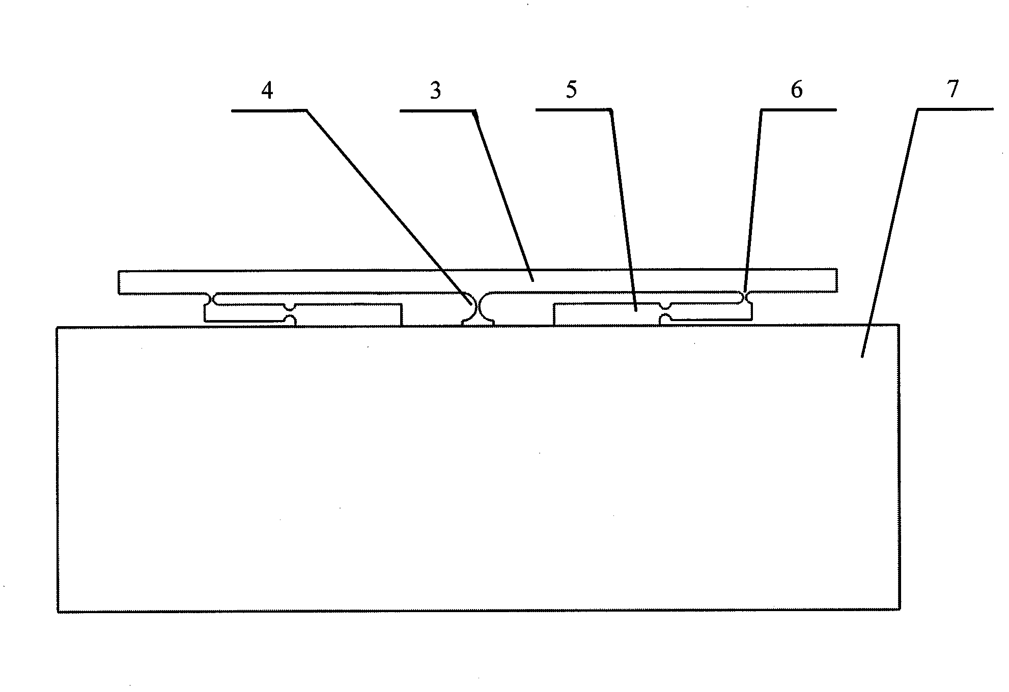
[0026] Such as figure 1 and figure 2 As shown, the flexible auxiliary arm tracking mirror of the present invention with ultra-high angular sensitivity and high frequency response micro-angular pendulum control includes: a mirror frame assembly, a flexible auxiliary arm following deflection mechanism, a driving mechanism, and a control system.

[0027] Mirror frame assembly: including reflector 1 and fixing part 2. Fixing part 2 fixes reflector 1 on the flexible auxiliary arm following deflection mechanism, and the angle deflection occurs with the deflection of the flexible auxiliary arm following the deflection mechanism, and the incident beam passes through reflector 1 After reflection, the angle deflection of the mirror 1 is controlled by controlling the flexible auxiliary arm to follow the deflection mechanism, so as to realize the directio...


PUM


Abstract

The invention discloses a micro angular swing control reflecting mirror followed by flexible auxiliary arms with superhigh angular sensitivity and high frequency response and belongs to a light beam control device. The micro angular swing control reflecting mirror comprises a mirror frame assembly, a flexible auxiliary arm followed deflection mechanism, a driving mechanism and a control system, wherein the mirror frame assembly is fixedly arranged on a rigid cross beam of the flexible auxiliary arm followed deflection mechanism; an incident light beam is emerged through a reflecting mirror inthe mirror frame assembly; the control system is used for controlling the driving mechanism to push the rigid cross beam, so that an angle of the reflecting mirror is deflected and the control over the direction of an emergent light beam is realized; a displacement sensor is used for feeding back corner information of the reflecting mirror to the control system; the flexible auxiliary arms are additionally arranged at the positions close to a piezoelectric ceramic driving point and are connected with the rigid cross beam through a pivot hinge; the pivot hinge is used for ensuring no deformityof the cross beam during deflection so as to realize the superhigh angular sensitivity; and the flexible auxiliary arms are used for providing a large auxiliary restoring force for the rigid cross beam during deflection to improve the dynamic response speed. The micro angular swing control reflecting mirror has the characteristics of high angular sensitivity and high dynamic track response speed.

Description

technical field [0001] The invention belongs to the technical field of light beam control, and mainly relates to a flexible auxiliary arm following a micro-angle pendulum control mirror with ultra-high angle sensitivity and high frequency response. Background technique [0002] Micro pendulum control mirrors are often used in optical systems to control the rapid angular deflection of light beams and realize the direction correction and stabilization of light beams. For example, in the adaptive optics system, it is used to correct the overall tilt of the beam front; in the field of wireless optical communication technology, it is used to achieve the alignment and stability of the beam; Tracking; used in the field of high-energy lasers and precision collimation to stabilize the beam direction. In the application of these optical systems, in order to improve the beam control accuracy and obtain good compensation, tracking and control effects, it is required that the beam fast ...

Claims


Application Information

Patent Timeline
Patent Type & Authority Applications(China)
IPC IPC(8): G02B26/08
Inventor 谭久彬朱凡崔继文
Owner HARBIN INST OF TECH
Why Eureka
Try Eureka