Novel electrical contact jack

A new type of electrical contact technology, applied in the direction of contact parts, etc., can solve the problem of low contact efficiency, achieve good plug performance, stable plug connection, and simple socket structure

Inactive Publication Date: 2012-02-15
CHINA NORTH IND GRP HANGLIAN TECH CO LTD
View PDF5 Cites 1 Cited by
  • Summary
  • Abstract
  • Description
  • Claims
  • Application Information

AI Technical Summary

Problems solved by technology

[0008] The invention provides a new type of electrical contact socket, which overcomes the defects that the existing leaf spring electrical contact socket cannot form surface contact and has low contact efficiency, and forms an effe

Method used


Image

  • Novel electrical contact jack
  • Novel electrical contact jack
  • Novel electrical contact jack

Examples


Embodiment Construction

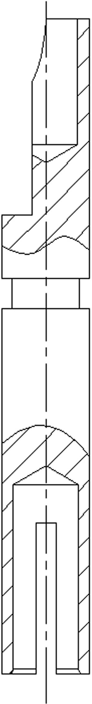
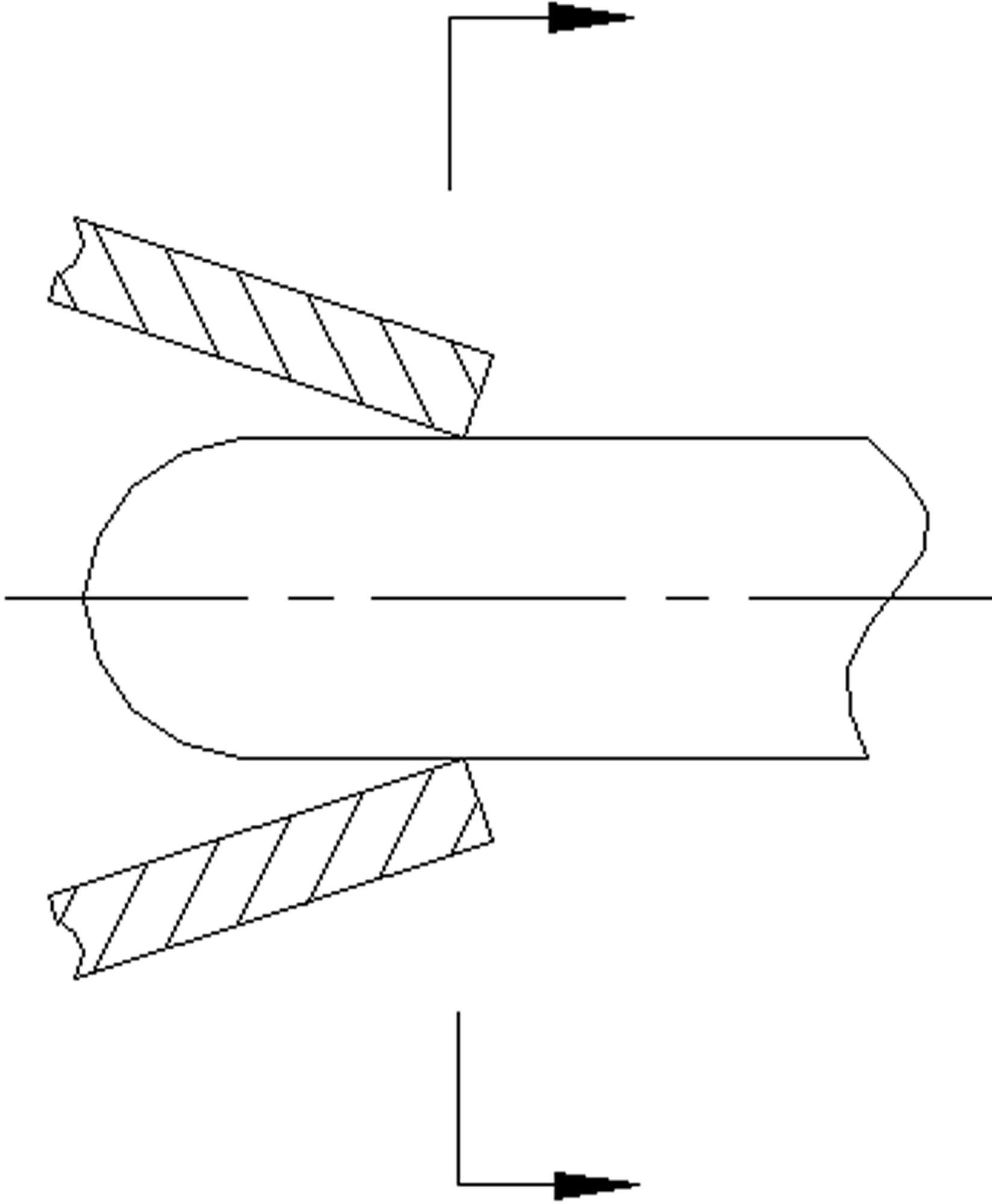
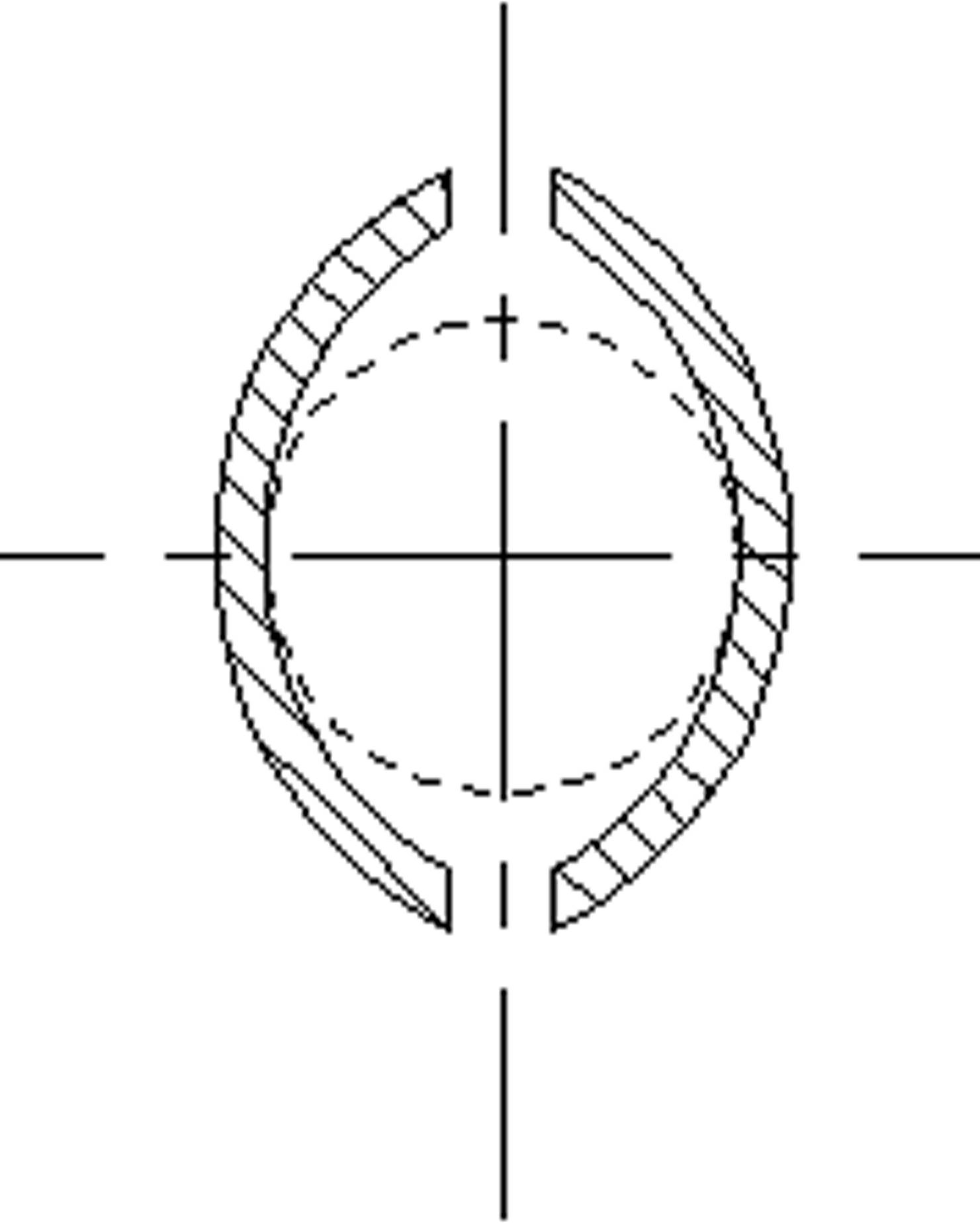
[0022] The present invention will be further described below in conjunction with accompanying drawing.

[0023] Figure 4 As shown, a new type of electrical contact jack includes a jack main body 1, a jack area 2 and a welding area 3, the jack area 2 and the welding area 3 are respectively arranged at the front and rear ends of the jack body 1, and the jack area 2 is provided with a slotted area 4 along the axial direction of the socket main body 1. The slotted area is symmetrically slotted from the insertion end of the welding area to the depth direction. The slot width is 0.5-0.6, the number of slots is 2-4, and the length of the slotted area = length of socket area - 1mm; cavity of socket area 2 is divided into contact area 5 and deep hole area 6 stepwise from outside to inside, the inner hole size of deep hole area 6 is larger than that of contact area 5, and the length of contact area Less than the length of the grooved area, the length of the deep hole area = the length...


PUM


Abstract

The invention relates to a novel electrical contact jack, which comprises a jack main body, a welding zone and a jack zone, wherein the jack zone and the welding zone are respectively arranged on the front end and the rear end of the jack main body, a slotting zone is formed on the jack zone along the axial direction of the jack main body, an inner cavity of the jack zone is stepwise divided into a contact zone and a longhole zone from outside in, and the inner bore size of the longhole zone is larger than that of the contact zone. The jack zone of the jack is formed by stepwise combining the contact zone with the longhole zone, the contact zone is fully utilized to realize the large-area contact of a cylinder formed when a pin is plugged in the jack, and the longhole zone is utilized to realize the correction of the concentricity deviation when the pin is plugged in the jack; the jack has a simple structure, is beneficial for the pin to be stably plugged in, and has good plug-in performance; and the service lives of the pin and the jack are prolonged.

Description

technical field [0001] The invention relates to a structure of an electric contact socket, in particular to a structure of the socket adapted to be mated with a circular electric contact pin. Background technique [0002] The structural form of the traditional electrical contact leaf spring socket (hereinafter referred to as the socket) is shown in Figure (1): the hole φD is opened on the main body of the socket to fit the pin, and φD is generally larger than the nominal size of the matching pin φE + 0.18 +0.13, the outer circle size of the pin is -0.01 -0.03 on the basis of its nominal size φE, slotted to close the mouth and form a leaf spring. The purpose of forming a gap between the contact inner hole φD of the socket and the outer circle φE of the adapter pin is to prevent the leaf spring from being excessively stretched and failing due to unavoidable process deviations when the pin and the socket are mated. [0003] from figure 2 , 3 It can be seen from the figure th...

Claims


Application Information

Patent Timeline
IPC IPC(8): H01R13/10H01R13/11
Inventor 叶学俊潘荣封燕李竹法
Owner CHINA NORTH IND GRP HANGLIAN TECH CO LTD
Why Eureka
Try Eureka