
Switch power controller and short-circuit protection method of current control end thereof

A switching power supply and current control technology, used in control/regulation systems, emergency protection circuit devices, instruments, etc., can solve the problems of linear increase, power switch SW cut-off, linear increase of Vcs signal, etc., to prevent continued rise, avoid burn effect

Active Publication Date: 2012-02-15
GIANTEC SEMICON LTD
View PDF3 Cites 19 Cited by
  • Summary
  • Abstract
  • Description
  • Claims
  • Application Information

AI Technical Summary

Problems solved by technology

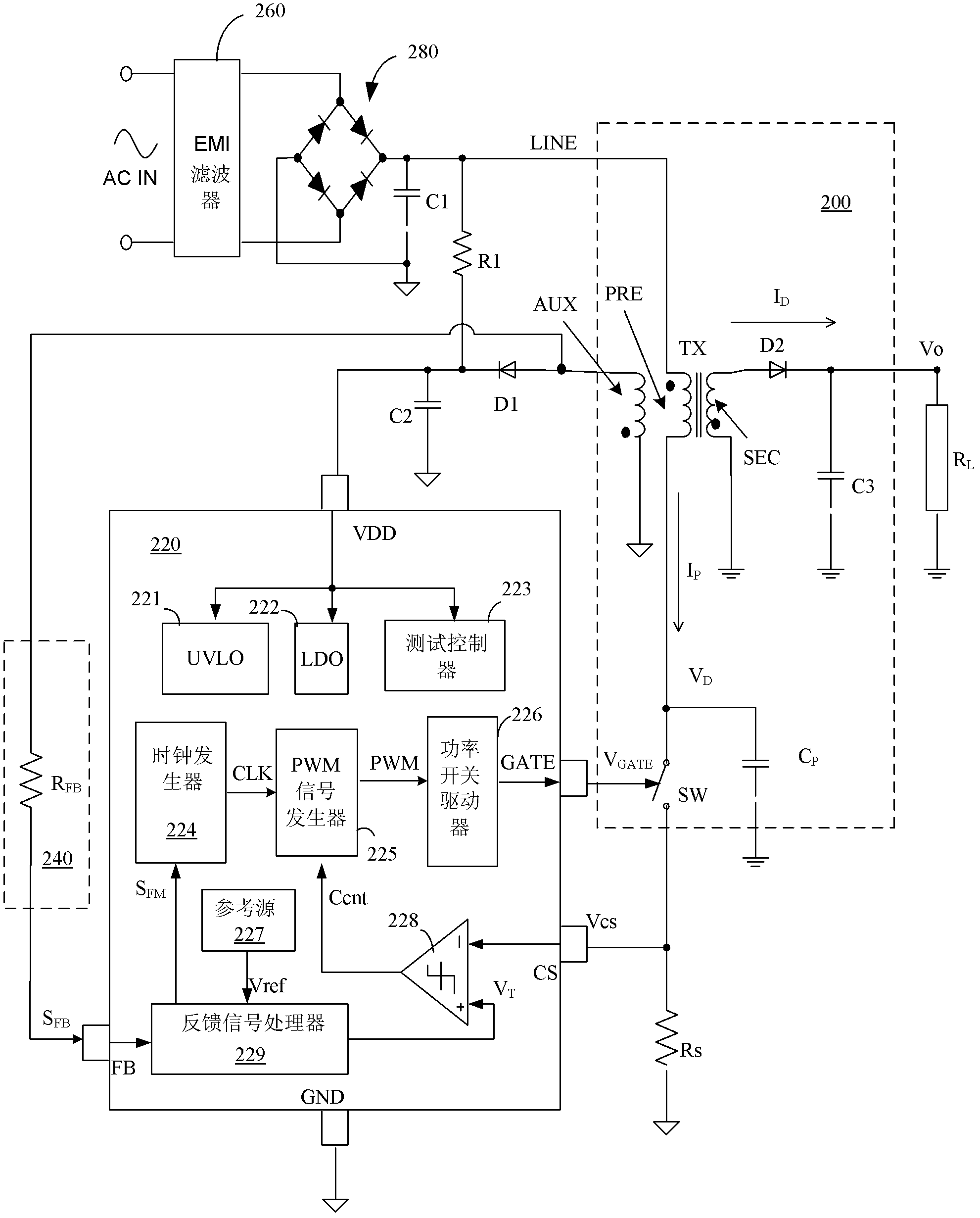
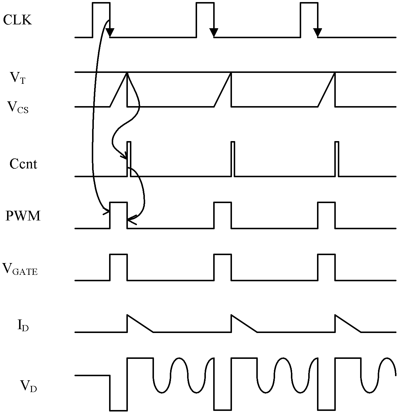
[0012] 2. The conduction of the power switch SW leads to the transformer primary side coil current I P Linear increase, which in turn leads to a linear increase in the Vcs signal;
[0013] 3. When the amplitude of the Vcs signal reaches the PWM comparator threshold V T When the magnitude of , the PWM comparator 228 flips, at this time the PWM signal becomes low, which in turn causes the power switch SW to be cut off;
[0014] 4. The power switch SW is cut off, causing the Vcs signal to return to zero, and the PWM comparator 228 is reversed;
[0017] The drawback of the above circuit is that if the CS pin is shorted, the transformer primary current I p will be due to the voltage on the CS pin failing to reach the threshold level V T Continue to increase until the transformer is saturated, and eventually burn the primary coil of the transformer

Method used


Image

  • Switch power controller and short-circuit protection method of current control end thereof
  • Switch power controller and short-circuit protection method of current control end thereof
  • Switch power controller and short-circuit protection method of current control end thereof

Examples


Embodiment Construction

[0050] The following embodiments of the present invention introduce protection for the current control terminal used to input the current control signal in the switching power supply controller. In each embodiment, the switching power supply controller is configured as an integrated circuit chip, but it can be understood that the switching power supply controller can still be composed of multiple chips, or constructed of discrete components. Moreover, the composition of the switching power supply controller is not limited to the specific example described in the embodiment, and its components can be added, subtracted or replaced.

[0051] Figure 4 A circuit block diagram of a flyback switching power supply system and its control chip according to an embodiment of the present invention is shown. exist Figure 4 The switching power supply system shown includes a switching power converter 400 , a switching power supply control chip 420 , a feedback network 440 , a current sign...


PUM


Abstract

The invention relates to a switch power controller and a short-circuit protection method of a current control end thereof, which are used for a switch power system. The method comprises the following steps of: generating a window signal with preset width while generating a PWM (Pulse Width Modulation) signal of the switch power controller; comparing a voltage of a current control signal input from the current control end of the switch power controller with a threshold voltage, and outputting a comparison voltage, wherein the voltage of the current control signal is gradually increased in the conduction period of the PWM signal; trigging the detection of the comparison voltage by the window signal, and determining whether to trigger a first reset signal according to the comparison voltage, wherein the first reset signal is used for carrying out resetting on the PWM signal of the current period; and triggering a second reset signal by hop of the comparison voltage, wherein the second reset signal is used for carrying out resetting on the PWM signal of the current period, and when the PWM signal is reset, a power switch is switched off by a power switch actuator, and thus primary side current of a transformer can be prevented from continuously increasing.

Description

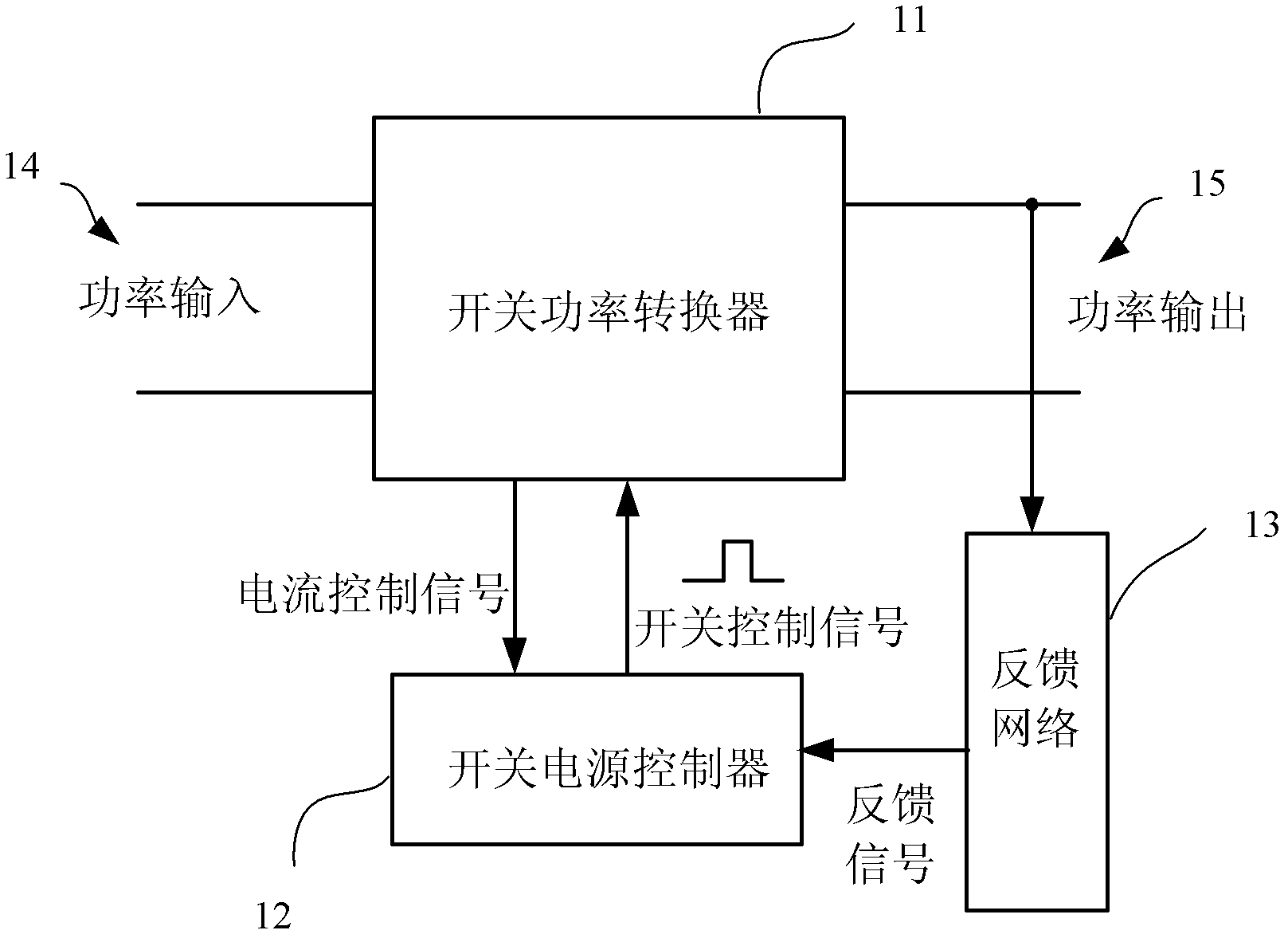
technical field [0001] The invention relates to the field of integrated circuits. More specifically, the present invention proposes a realization method for short-circuit protection of the current control terminal. Background technique [0002] Due to many advantages compared with traditional linear power supplies, such as higher efficiency, lower standby power consumption, lower cost, smaller size and lighter weight, switching power supplies are more and more widely used Used in various electronic equipment. [0003] figure 1 The basic block diagram of the most widely used current mode switching power supply system is shown. The system includes a switching power converter 11 , a switching power supply controller 12 , a feedback network 13 , a power input port 14 , and a power output port 15 . The function of the system is to convert the alternating current (AC) power or direct current (DC) power input from the power input port 14 into direct current (DC) or alternating ...

Claims


Application Information

Patent Timeline
IPC IPC(8): H02H7/12H02M7/217H02M3/335
Inventor 王为黄剑锋杨彪朱臻沈国平吴一一王多慧
Owner GIANTEC SEMICON LTD
Learn More