
Energy feedback elevator system

An elevator system and energy feedback technology, applied in the direction of AC network voltage adjustment, reactive power compensation, elevators, etc., can solve the problems that are not conducive to product market competition and increase the cost of elevators, so as to avoid large losses, improve service life and reduce losses Effect

Active Publication Date: 2012-02-15
HITACHI ELEVATOR CHINA
View PDF3 Cites 5 Cited by
  • Summary
  • Abstract
  • Description
  • Claims
  • Application Information

AI Technical Summary

Problems solved by technology

This practice will undoubtedly greatly increase the cost of the elevator, which is not conducive to the market competition of products.

Method used


Image

  • Energy feedback elevator system
  • Energy feedback elevator system
  • Energy feedback elevator system

Examples


Embodiment 1

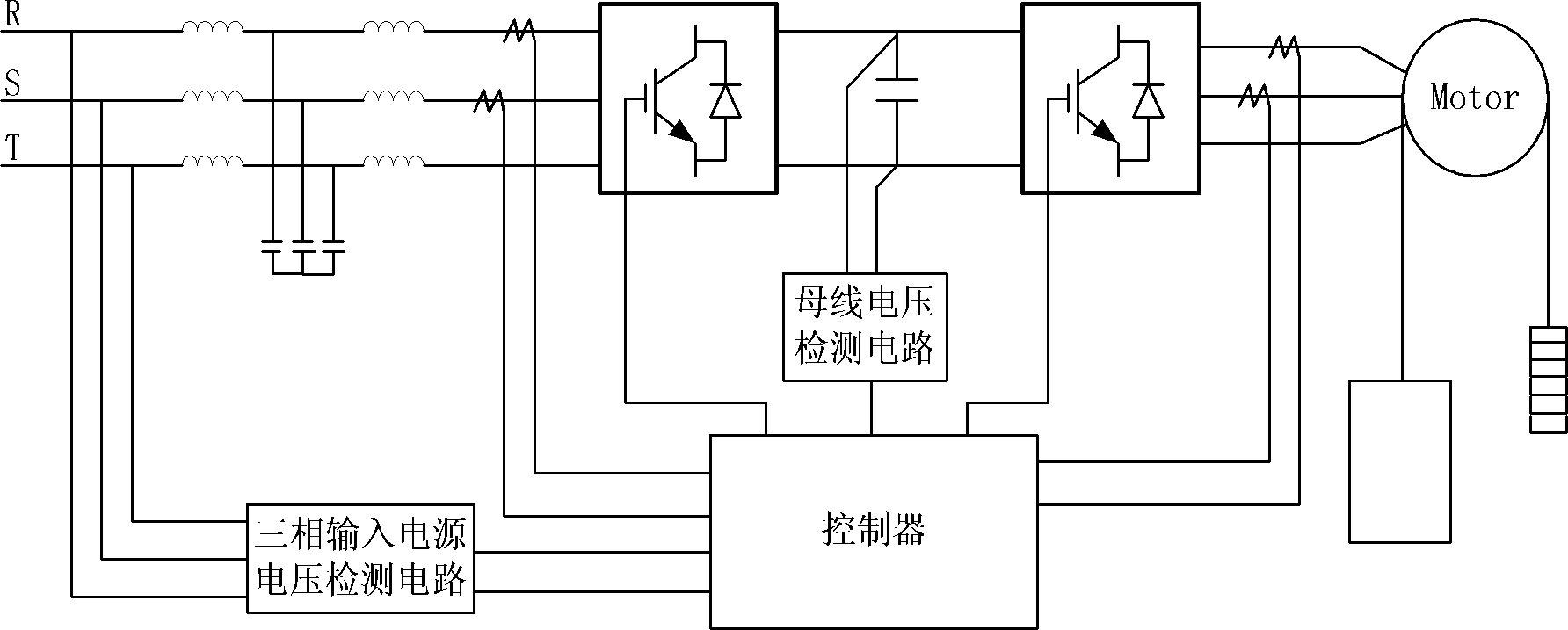
[0017] figure 1 It is a schematic diagram of the structure of the energy feedback elevator system of the present invention when it is applied to a series energy feedback elevator system. In addition to the boost filter device and the current sensor on the input side of the three-phase controllable rectifier in the existing energy feedback elevator system, the energy feedback elevator system , three-phase controllable rectifier, DC bus capacitor, three-phase inverter, current sensor on the output side of the three-phase inverter, bus voltage detection circuit and controller, also includes a three-phase input power supply voltage detection circuit, such as figure 1 As shown, the input terminal of the three-phase input power supply voltage detection circuit is connected to the three-phase power supply input terminals R, S, T, and the output terminal is connected to the controller.

[0018] The three-phase input power supply voltage detection circuit is used to detect the maximum ...

Embodiment 2

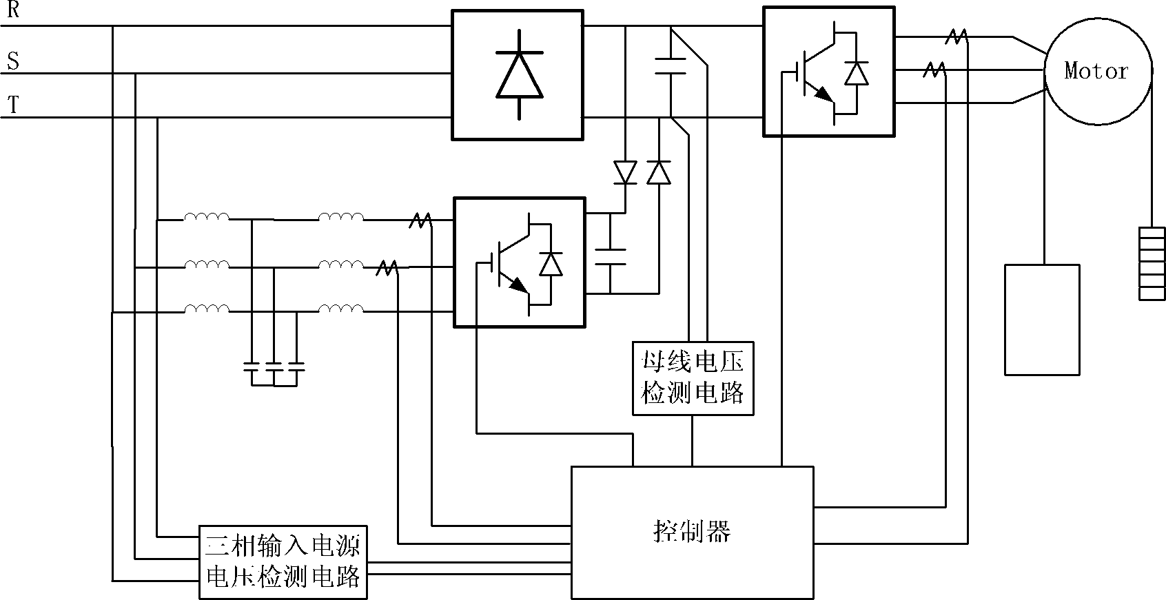
[0026] figure 2 A schematic structural diagram of another energy feedback elevator system provided by the present invention. This system is applied to a parallel energy feedback elevator system. In addition to including a three-phase uncontrollable rectifier bridge, a boost filter device, and a three-phase controllable rectifier input side In addition to the current sensor, three-phase controllable rectifier, power diode module, DC bus capacitor, three-phase inverter, current sensor on the output side of the three-phase inverter, bus voltage detection circuit and controller, it also includes three-phase input A power supply voltage detection circuit, the input terminal of the three-phase input power supply voltage detection circuit is connected to the three-phase power supply input terminals R, S, T, and the output terminal is connected to the controller.

[0027] The three-phase input power supply voltage detection circuit is used to detect the maximum value of the three-pha...


PUM


Abstract

The invention discloses an energy feedback elevator system. The energy feedback elevator system applied to a tandem topological structure is taken as an example, and the system comprises a booster filter device, a current sensor at an input side of a three-phase controlled rectifier, the three-phase controlled rectifier, a direct current (DC) bus capacitor, a three-phase inverter, a current sensor at an output side of the three-phase inverter, a bus voltage detection circuit, a controller and a three-phase input power supply voltage detection circuit, wherein, the input end of the three-phaseinput power supply voltage detection circuit is connected with input ends R, S and T of a three-phase power supply, and the output end of the three-phase input power supply voltage detection circuit is connected with the controller. The energy feedback elevator system has the beneficial effects that bus voltage is dynamically adjusted by detecting change of three-phase power supply voltage without adopting a fixed bus voltage mode, thus greatly lowering loss of the three-phase controlled rectifier and the three-phase inverter, prolonging the service life of the three-phase controlled rectifier and the three-phase inverter, reducing the cost, achieving positive economic benefit and being beneficial to market competition of the product.

Description

technical field [0001] The invention belongs to the technical field of elevator energy saving, in particular to an elevator system with energy feedback. Background technique [0002] With the continuous improvement of national energy conservation and emission reduction policies and the continuous improvement of the legal system, elevators with energy feedback functions have quietly become the online products of major elevator manufacturers. At present, elevator products with energy feedback can be generally divided into two categories: one adopts series topology, and the other adopts parallel topology. Although the two topologies have their own characteristics, they both need to ensure that the bus voltage is higher than the peak value of the three-phase input power voltage in order to achieve bidirectional energy flow and power factor correction (PFC, Power Factor Correction). Therefore, in order to adapt to different three-phase input power supply voltage levels and allow...

Claims


Application Information

Patent Timeline
Patent Type & Authority Applications(China)
IPC IPC(8): H02J3/12H02J3/18B66B1/30
CPCY02E40/30
Inventor 郭志海郭威刘超文杜永聪张文俊
Owner HITACHI ELEVATOR CHINA
Learn More