Brake control method for permanent magnet synchronous motor

A permanent magnet synchronous motor and brake control technology, applied in the direction of the stop device, etc., can solve the problems of the inverter's power module damage, uncontrollable, poor braking performance, etc., to eliminate the influence of the inverter bus voltage and increase the bus voltage. Voltage, the effect of ensuring braking performance

Active Publication Date: 2012-07-18
WUXI ECOVI TECH
View PDF0 Cites 0 Cited by
  • Summary
  • Abstract
  • Description
  • Claims
  • Application Information

AI Technical Summary

Problems solved by technology

However, the existing permanent magnet synchronous motor winding short-circuit braking method cannot control the process of converting the mechanical energy of the permanent magnet synchronous motor into heat energy, so it cannot ensure that the braking torque generated by it is always the maximum braking torque, that is, it cannot automatically track the permanent magnet synchronous motor. The maximum braking torque, the braking performance is poor, and in the case of power failure (i.e. AC power failure), the bus voltage of the inverter drops rapidly, which cannot guarantee the smooth completion of the braking process, so the braking performance of the permanent magnet synchronous motor cannot Ensure that it may even cause damage to the power module of the inverter. To solve the brake of the permanent magnet synchronous motor in the case of power failure, it is necessary to set up other complicated control methods to achieve

Method used


Image

  • Brake control method for permanent magnet synchronous motor
  • Brake control method for permanent magnet synchronous motor
  • Brake control method for permanent magnet synchronous motor

Examples


Embodiment Construction

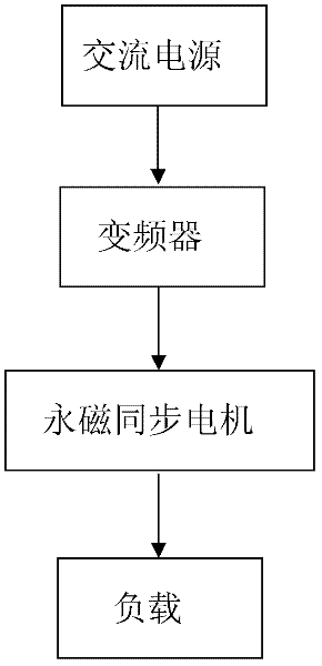
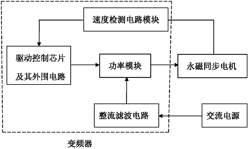
[0030] Such as figure 1 As shown, the application system of the present invention is composed of an AC power supply, a frequency converter, a permanent magnet synchronous motor and a load connected in sequence, such as figure 2 As shown, the frequency converter includes a rectification and filtering module, a drive control chip and its peripheral circuit modules, a speed detection module, and an IGBT or IPM power module. Controlled by the drive control chip and its peripheral circuits, the drive control chip and its peripheral circuit modules output the PWM signal, and the IGBT or IPM power module converts the PWM signal into a voltage and outputs it to the permanent magnet synchronous motor. In order to detect the speed of the permanent magnet synchronous motor in real time, in There is also a speed detection module between the permanent magnet synchronous motor and the drive control chip and its peripheral circuit modules, so that the drive control chip and its peripheral c...


PUM


Abstract

The invention relates to a brake control method for a motor, in particular to the brake control method for a permanent magnet synchronous motor. The method is applied to a system consisting of an alternating current power supply, a frequency converter, the permanent magnet synchronous motor and a load. The control method comprises the following steps of: (1) determining voltage amplitude and a voltage angle during the braking of the permanent magnet synchronous motor; and (2) controlling the output voltage of the frequency converter based on the determined voltage amplitude and the determinedvoltage angle, and automatically tracking the maximum braking torque of the permanent magnet synchronous motor on the premise of ensuring that the bus voltage of the frequency converter is constant or tends to be constant to ensure the braking performance of the permanent magnet synchronous motor. The braking of the permanent magnet synchronous motor under normal power supply and power failure conditions is met by adopting the same algorithm at the same time, so the algorithm is simplified.

Description

technical field [0001] The invention relates to a motor brake control method, in particular to a permanent magnet synchronous motor brake control method, which is applied to a system composed of an AC power supply, a frequency converter, a permanent magnet synchronous motor and a load. Background technique [0002] The so-called permanent magnet synchronous motor refers to a synchronous motor using a permanent magnet pole rotor. Its application system is mainly composed of an AC power supply, a frequency converter, a permanent magnet synchronous motor and a load. Conventional permanent magnet synchronous motor braking methods generally use mechanical brakes, that is, an additional mechanical device locks the rotor shaft of the permanent magnet synchronous motor or its driven parts to achieve braking. If the brake fails, the braking performance of the permanent magnet synchronous motor cannot be guaranteed, and there is a great potential safety hazard. Considering the above-...

Claims


Application Information

Patent Timeline
Patent Type & Authority Patents(China)
IPC IPC(8): H02P6/24
Inventor 何志明王明仁周文忠黄雨
Owner WUXI ECOVI TECH
Why Eureka
Try Eureka