Double compensation method and device for moving tilt of numerical control floor type boring-milling machine ram

A compensation method, floor boring technology, which is applied in the field of CNC machine tools, can solve problems such as low compensation accuracy, excessive deformation of the spindle box, and uncompensated ram, and achieve high compensation accuracy, good effect, and small size.

Inactive Publication Date: 2012-02-22
SHANGHAI SANY PRECISION MACHINERY
View PDF5 Cites 18 Cited by
  • Summary
  • Abstract
  • Description
  • Claims
  • Application Information

AI Technical Summary

Problems solved by technology

[0009] The disadvantage of the first three compensation methods is that the compensation is mainly through the deformation of the spindle box or ram due to external force, which often results in the situation that the deformation of the spindle box is too large but the ram is not compensated, and the compensation amount cannot be accurate control, low compensation accuracy
Compared with the first three methods, the fourth method has the characteristics of wide compensation range and high precision, but the oil pressure control method of the variable pressure hydraulic chamber is more cumbersome and difficult to implement
[0013] Among the above-mentioned prior art, the hydraulic compensation device provided by Patent No. CN200810187286 is relatively complicated, and the oil pressure control method of the variable pressure hydraulic chamber is relatively complicated and difficult to implement; Patent No. The relationship between pressure and stick out

Method used


Image

  • Double compensation method and device for moving tilt of numerical control floor type boring-milling machine ram
  • Double compensation method and device for moving tilt of numerical control floor type boring-milling machine ram
  • Double compensation method and device for moving tilt of numerical control floor type boring-milling machine ram

Examples


Embodiment Construction

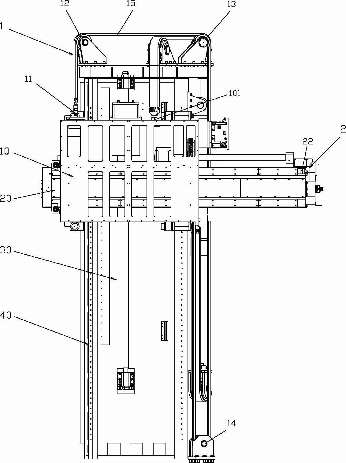
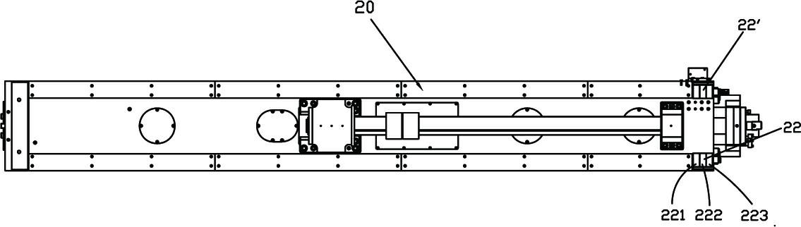
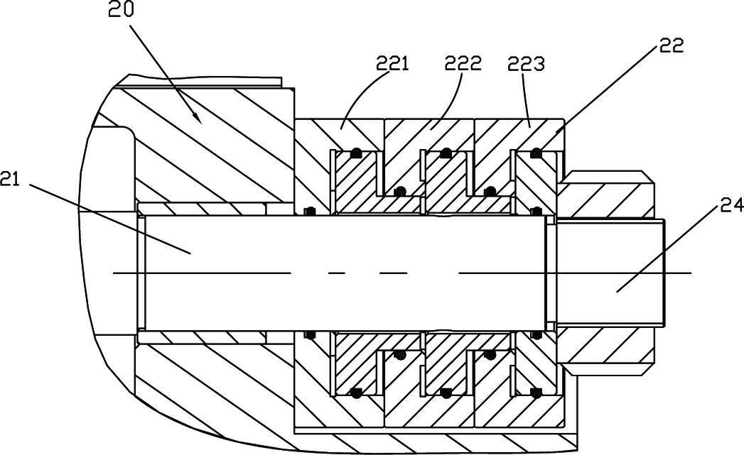
[0046] see Figure 1 to Figure 5 , a dual compensation device for the movement and inclination of the ram of a CNC floor boring and milling machine according to the present invention includes a headstock 10 inclination compensation mechanism 1 and a ram 20 deformation compensation mechanism 2 .

[0047] The headstock tilt compensation mechanism 1 includes a compensation hydraulic cylinder 11, which is arranged on one side of the upper end surface of the headstock 10 running on the guide rail 40 of the column 30, that is, on the other side relative to the headstock lifting point 101, the lifting point 101 is set At the position of the center of gravity of the main shaft box in the state where the main shaft does not extend; the first and second fixed pulleys 12, 13, wherein the first fixed pulley 12 is arranged on the top or upper part of the column 30 on the side of the corresponding compensation hydraulic cylinder 11 through a fixed bracket , the second fixed pulley 13 is arr...


PUM


Abstract

Provided is a double compensation method and a device for moving tilt of a numerical control floor type boring-milling machine ram. The method includes that 1) a spindle box is provided with a spindle box tilt compensation mechanism and the ram is provided with a ram droop compensation mechanism, 2) ram droop quantity and spindle box tilt degree of all compensation points of the horizontal direct, namely a Z axis of the ram is measured through measurement tools, and measured data is input in a programmable logic controller, 3) coordinate value of the ram on the Z axis is detected by a detection element during operation of a machine tool, 4) corresponding ram droop quantity and spindle box tilt degree are looked up in the programmable logic controller according to the detected coordinate value, and 5) each coordinate value is calculated according to the ram droop quantity and the spindle box tilt degree and converted to compensation voltage, then compensation voltage signals are output to an electro-hydraulic proportional valve after being amplified by an amplifier, and the electro-hydraulic proportional valve controls a deformation compensation mechanism arranged on the ram and an inclination compensation mechanism of the spindle box.

Description

technical field [0001] The invention relates to a numerically controlled machine tool, in particular to a double compensation method and device for moving and tilting a ram of a numerically controlled floor boring and milling machine. Background technique [0002] With the continuous development of modern manufacturing industry, the importance of precision and ultra-precision machining technology has become increasingly prominent. As an important equipment in the manufacturing industry, CNC machine tools are also facing opportunities and challenges in the new era. Improving the precision of CNC machine tools is the key to improving the quality of CNC machine tools and enhancing market competitiveness. [0003] The most important structural feature of floor boring and milling machine is the use of cantilevered ram working parts. The ram is in an overhang state when it is working, and the greater the working stroke, the greater the maximum overhang. Due to the weight of the...

Claims


Application Information

Patent Timeline
Patent Type & Authority Applications(China)
IPC IPC(8): B23Q23/00
Inventor 杨阳邢雨宋宏伟
Owner SHANGHAI SANY PRECISION MACHINERY
Why Eureka
Try Eureka