
Ventilated rain removal grating for train air-conditioning system

An air-conditioning system and train technology, applied in sustainable transportation, railway car body parts, railway vehicle heating/cooling, etc., can solve the problem that rainwater cannot be completely prevented from entering, and achieve simple structure, improved exhaust capacity, and increased contact area effect

Inactive Publication Date: 2012-02-22
西安飞豹科技有限公司
View PDF5 Cites 4 Cited by
  • Summary
  • Abstract
  • Description
  • Claims
  • Application Information

AI Technical Summary

Problems solved by technology

The ventilating and rain-removing grille in the form of louvers has the following disadvantages: during the running of a fast and high-speed train, when entering a tunnel or when two trains meet, the air pressure outside the car body changes suddenly, causing a series of problems to the environment inside the car. impact, and, when fresh air is supplied in rainy days, it is impossible to completely prevent the entry of rainwater

Method used


Image

  • Ventilated rain removal grating for train air-conditioning system
  • Ventilated rain removal grating for train air-conditioning system
  • Ventilated rain removal grating for train air-conditioning system

Examples


Embodiment 1

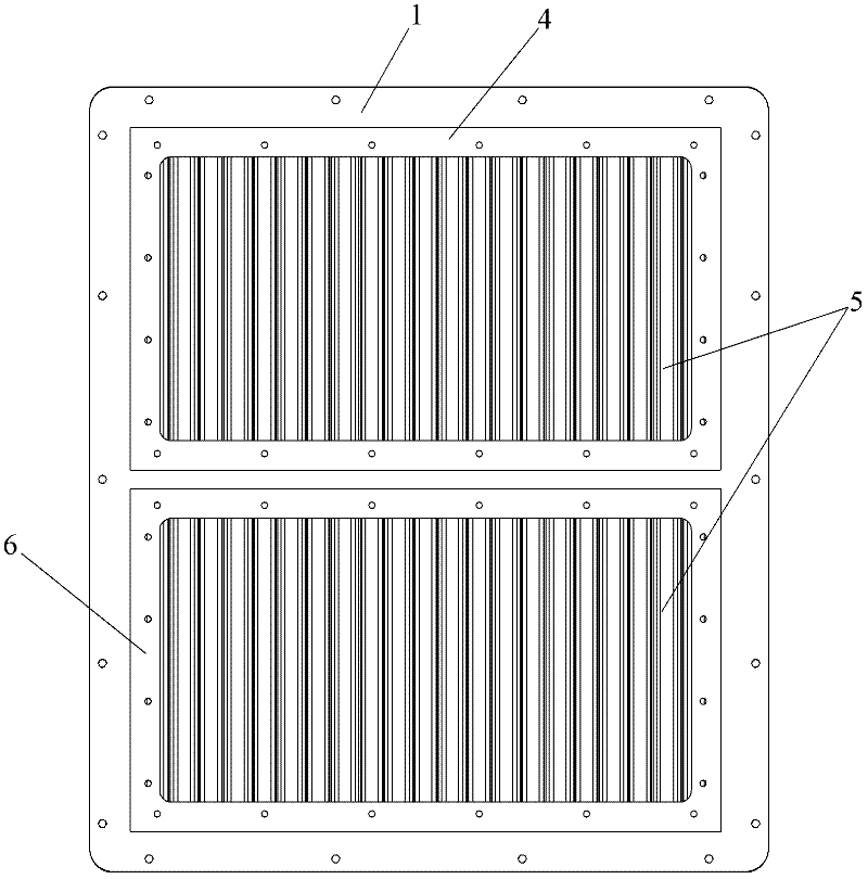
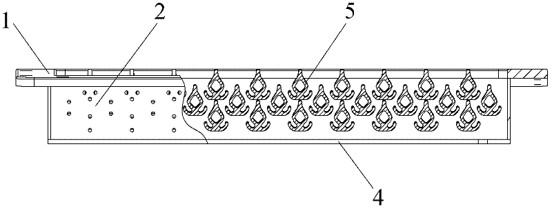
[0039] like figure 1 , figure 2 , image 3 , Figure 4 and Image 6 The ventilation and rain-removing grille for a train air-conditioning system includes a grille frame installed on the outside of the train compartment, and the grille frame is provided with an air inlet channel and an air exhaust channel, and the air inlet channel is connected with the inside of the train. The air supply fan of the air conditioning unit is connected, and the exhaust channel is connected with the exhaust fan of the air conditioning unit in the train. A plurality of rain-proof and pressure-resistant components 5 are arranged in the air inlet channel and the air exhaust channel. In the present invention, by arranging a plurality of rain-proof and pressure-resistant components 5 in the air inlet passage and the air exhaust passage, it is possible to make when the fast and high-speed train is running, when the train enters the tunnel and the two cars meet, due to the external air pressure of th...

Embodiment 2

[0046] like Figure 5 As shown, the difference between this embodiment and Embodiment 1 is only that: the upper ends of the multiple rain-proof and pressure-resistant components 5 in the air inlet passage are all inclined to the inside of the train; The lower ends of 5 all incline towards the train interior. The advantage of setting like this is: because this ventilating and rain-removing grille is arranged under the car window, the upper ends of a plurality of rain-proof and pressure-resisting components 5 in the air-intake channel are all inclined to the inside of the train, which can increase the contact area between the air-intake channel and the air , the air intake capacity of the air intake channel is enhanced, and the lower ends of the multiple rain-proof and pressure-resistant components 5 in the exhaust channel are all inclined to the inside of the train, which reduces the contact area between the exhaust channel and the air, and improves the discharge capacity of th...


PUM


Abstract

The invention discloses a ventilated rain removal grating for a train air-conditioning system. The ventilated rain removal grating comprises a grating frame arranged at the outer side of a train coach, wherein an air intake channel and an air exhaust channel are arranged on the grating frame; the air intake channel is connected with an air supply fan of an air conditioning unit in a train; the air exhaust channel is connected with an air exhaust fan of the air conditioning unit in the train; and a plurality of rain-keepoff and pressure-resisting components are all arranged in the air intake channel and the air exhaust channel. The ventilated rain removal grating can play a buffering role on airflow when air pressure outside the car body changes suddenly, and can prevent rain water from entering when fresh air is supplied in rain weather. The ventilated rain removal grating has the advantages of simple structure, convenience for use, low production cost and convenience for popularization and use.

Description

technical field [0001] The invention relates to a ventilating and rain-removing grille, in particular to a ventilating and rain-removing grille for a train air-conditioning system. Background technique [0002] In recent years, with the rapid development of China's economy, various fast and high-speed trains are increasing in the country. The train air conditioning system provides passengers with a comfortable riding environment, which has become an essential requirement for fast and high-speed trains. The air conditioning system consists of a compressor, a condenser, an expansion valve, and an evaporator to form a refrigeration circuit, which exchanges heat with the air in the car and provides a comfortable environment for the passengers in the car. In order to maintain a good air quality inside the train, the indoor unit is designed with vents, and the air is exchanged through the air supply fan and the exhaust fan. The ventilation and rain removal grille is installed on t...

Claims


Application Information

Patent Timeline
IPC IPC(8): B61D27/00
CPCY02T30/00
Inventor 蔺永良王小军董婷李雅利王鹏
Owner 西安飞豹科技有限公司
Learn More