Residual ammonia water degreasing method

A technology for removing oil and residual ammonia with ammonia water, applied in the field of machinery, can solve the problems of reduced processing efficiency, high water tar content, poor tar effect, etc., and achieve the effects of reducing impact, reducing the number of tar residue cleaning, and reducing labor intensity

Inactive Publication Date: 2012-02-22
HEILONGJIANG JIANLONG IRON & STEEL
View PDF5 Cites 6 Cited by
  • Summary
  • Abstract
  • Description
  • Claims
  • Application Information

AI Technical Summary

Problems solved by technology

[0009] The purpose of the present invention is to solve the bad effect of the tar in the existing process for treating residual ammonia water. Only the remaining ammonia water tank is used to process all the remaining ammonia water, and its effective volume is small, and the processing efficiency is reduced; often, the sub-pipelines of the tar device are blocked and the tar device turns inside out. The plate shaft is stagnant and the tar content of the treated water is high, and a method for degreasing residual ammonia water is provided

Method used


Image

  • Residual ammonia water degreasing method
  • Residual ammonia water degreasing method
  • Residual ammonia water degreasing method

Examples


specific Embodiment approach 1

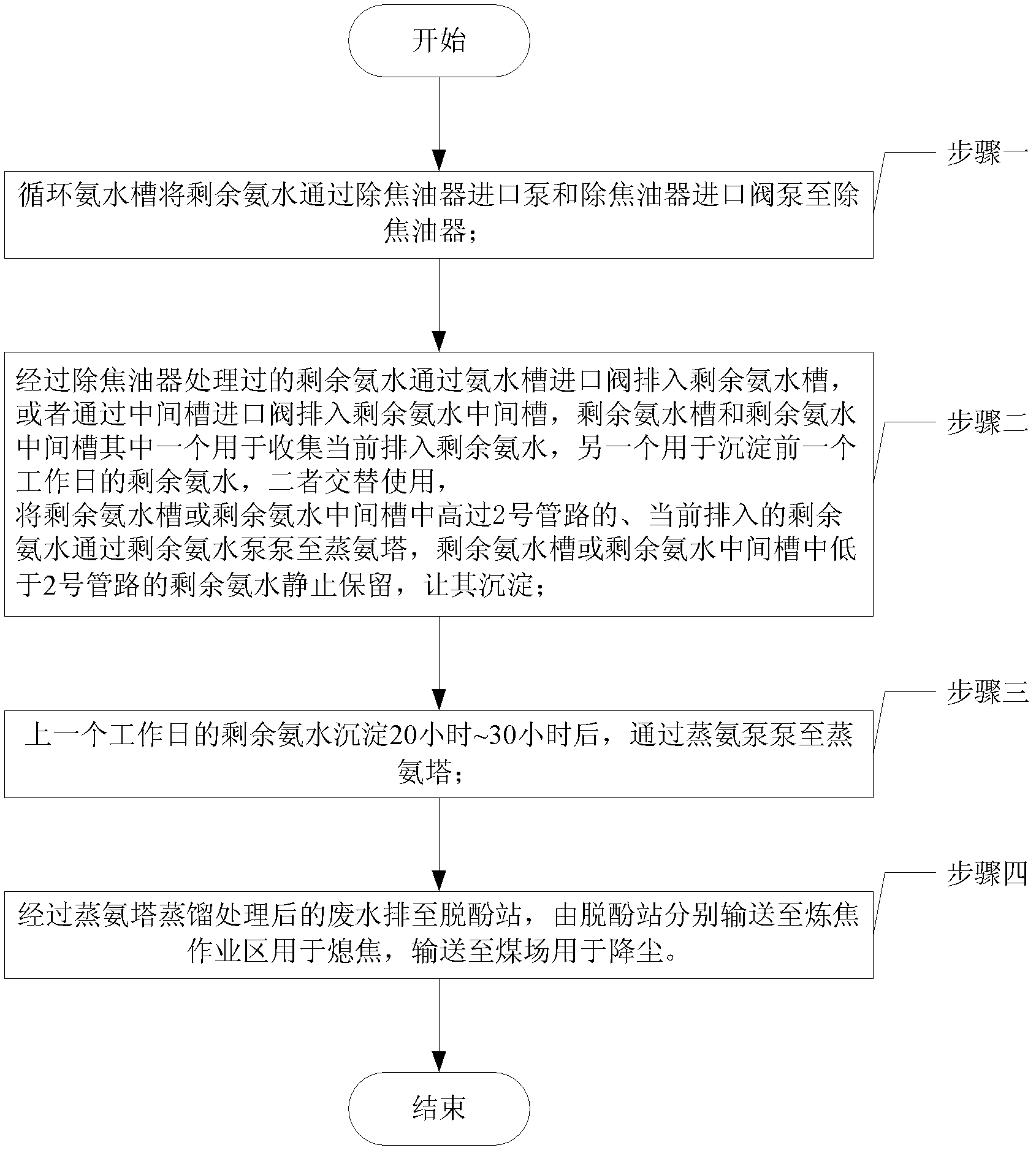
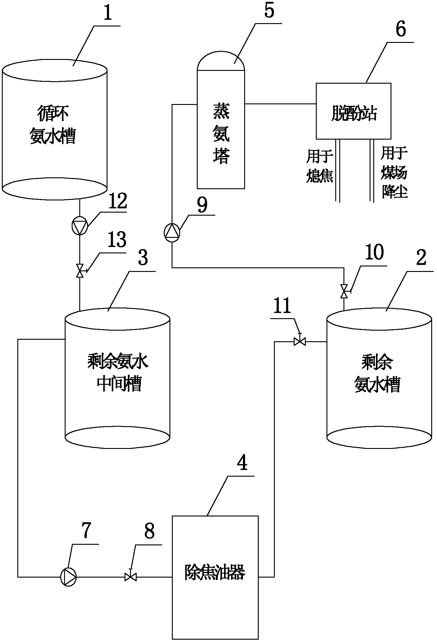
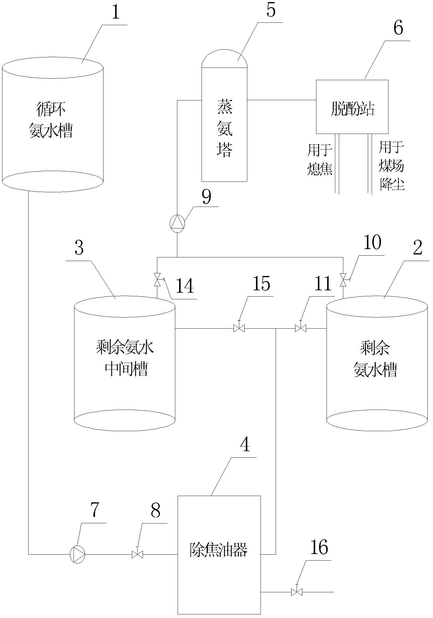
[0023] Specific implementation mode one: the following combination figure 1 and image 3 Describe this embodiment mode, a kind of remaining ammonia water degreasing method described in this embodiment, the device that this method uses comprises circulating ammonia water tank 1, remaining ammonia water tank 2, remaining ammonia water intermediate tank 3, tar remover 4, ammonia distillation tower 5, Dephenol removal station 6, tar remover inlet pump 7, tar remover inlet valve 8, residual ammonia water pump 9, ammonia water tank outlet valve 10, ammonia water tank inlet valve 11, middle tank outlet valve 14 and middle tank inlet valve 15,

[0024] The circulating ammonia water tank 1 and the inlet of the tar remover 4 are connected through the No. 1 pipeline, and the inlet pump 7 of the tar remover and the inlet valve 8 of the tar remover are arranged on the No. 1 pipeline, and the outlet of the tar remover 4 is connected with the residual ammonia The water tanks 2 are communic...

specific Embodiment approach 2

[0073] Specific implementation mode 2: This implementation mode further explains the implementation mode 1. The No. 1 pipeline is a DN80 pipeline with a length of 8 m to 15 m.

specific Embodiment approach 3

[0074] Embodiment 3: This embodiment further explains Embodiment 2. The inlet valve 8 of the tar remover is a DN80 valve.


PUM


Abstract

The invention provides a residual ammonia water degreasing method belongs to the field of machinery. The invention aims to solve the problems of the existing process for treating residual ammonia water that the tar treatment effect is bad, only a residual ammonia water tank is used for treating all the residual ammonia water, the effective volume is small and the treatment efficiency is reduced; and the branched pipes of a tar-removing device are always blocked, a turning plate rotation shaft in a tar precipitator moves sluggishly and the tar content of the treated water is high. The method comprises the following steps: 1) pumping the residual ammonia water to the tar-removing device by the circulating ammonia water tank; 2) discharging the water treated by the tar-removing device into the residual ammonia water tank or a residual ammonia water intermediate tank, pumping the residual ammonia water which is higher than a pipeline 2 in the tank into an ammonia distillation tower, and standing the residual ammonia water which is lower than the pipeline 2 to precipitate; 3) precipitating the residual ammonia water for 20-30 hours and then pumping into the ammonia distillation tower; and 4) discharging the wastewater treated by the ammonia distillation tower into a dephenolization station, and delivering the wastewater to the coking operation area for quenching and the coal yard for dust removal respectively by virtue of the dephenolization station.

Description

technical field [0001] The invention relates to a method for removing oil from residual ammonia water, which belongs to the field of machinery. Background technique [0002] The standard content of tar in the residual ammonia water tank of the coking plant should be less than 150mg / L. However, on-site sampling and testing showed that the tar content was as high as 324mg / L, far exceeding the standard content. Therefore the coking plant will carry out detarring process to remaining ammonia water, and existing a kind of remaining ammonia water degreasing method is as figure 2 As shown, the device includes circulating ammonia water tank 1, residual ammonia water tank 2, residual ammonia water intermediate tank 3, tar remover 4, ammonia distillation tower 5, phenol removal station 6, tar remover inlet pump 7, tar remover inlet valve 8 , residual ammonia water pump 9, ammonia water tank outlet valve 10, ammonia water tank inlet valve 11, circulating ammonia water tank outlet pump...

Claims


Application Information

Patent Timeline
Patent Type & Authority Applications(China)
IPC IPC(8): C02F9/10C01C1/10C02F1/40
Inventor 丛巍李侠丁爽姚本金
Owner HEILONGJIANG JIANLONG IRON & STEEL
Why Eureka
Try Eureka