Annular shield machine and tunnel construction method

A shield machine, annular technology, applied in the direction of tunnel, tunnel lining, earth drilling and mining, etc., to achieve the effect of reducing the opportunity of use and easy stability

Active Publication Date: 2012-02-22
SHANGHAI TUNNEL ENG CO LTD +1
View PDF5 Cites 18 Cited by
  • Summary
  • Abstract
  • Description
  • Claims
  • Application Information

AI Technical Summary

Problems solved by technology

[0004] However, the current manufacturing process, design and construction level limit the development of shield tunnels with larger diameters. In order to overcome this problem and realize the construction of larger tunnel sections, the present invention innovatively proposes

Method used


Image

  • Annular shield machine and tunnel construction method
  • Annular shield machine and tunnel construction method
  • Annular shield machine and tunnel construction method

Examples


Embodiment Construction

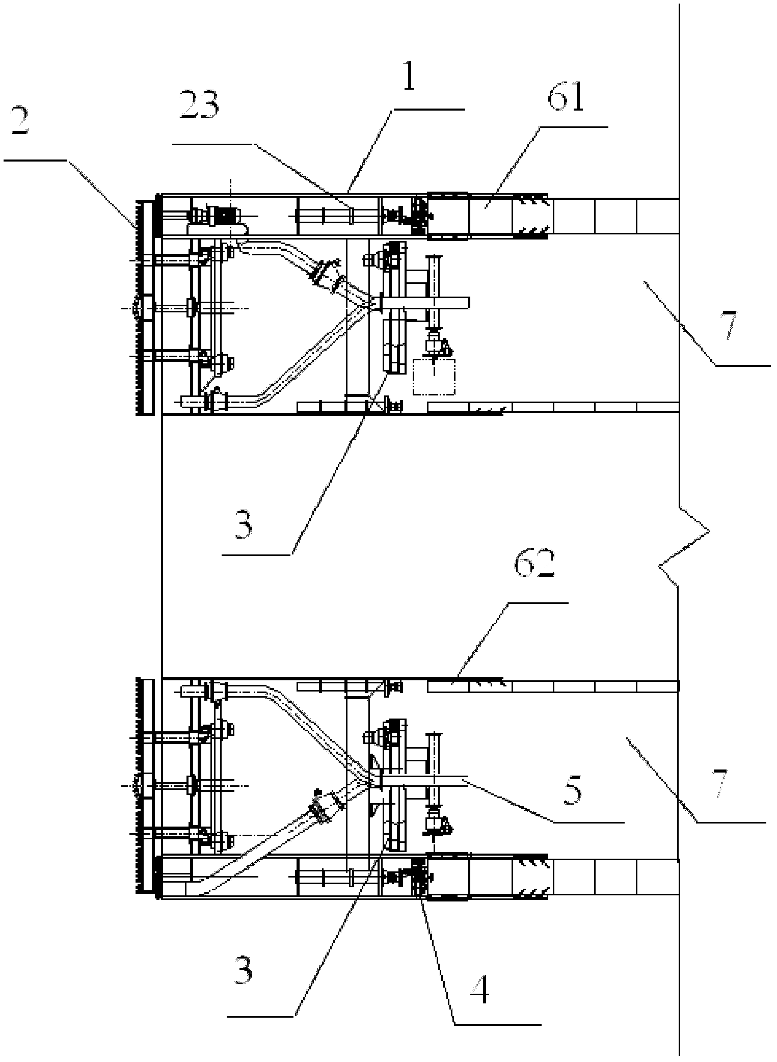
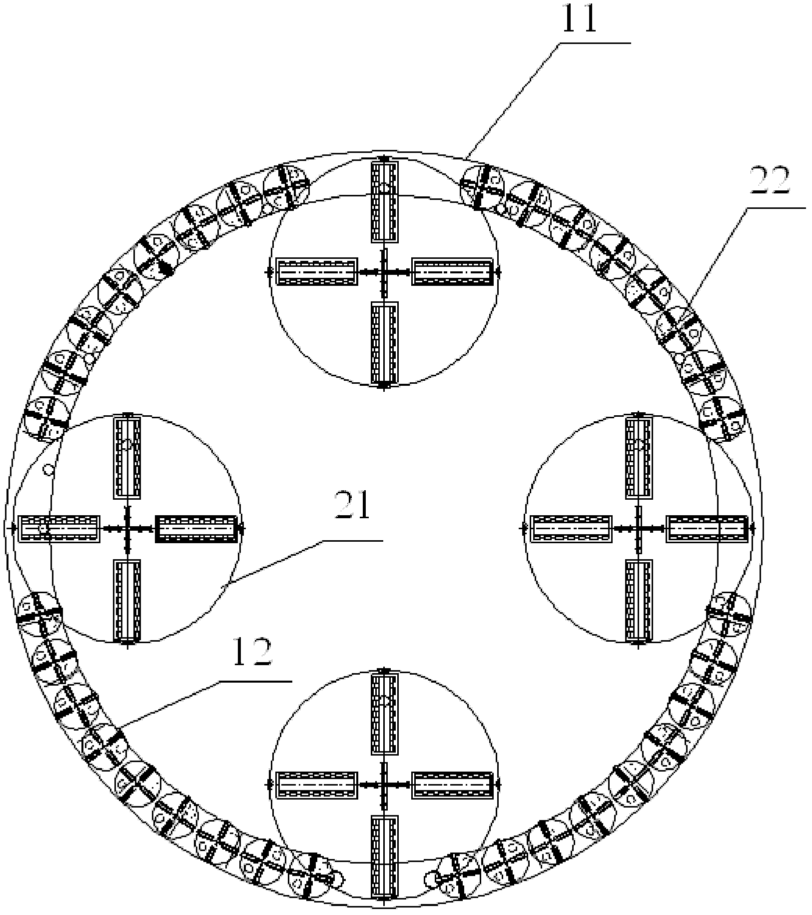
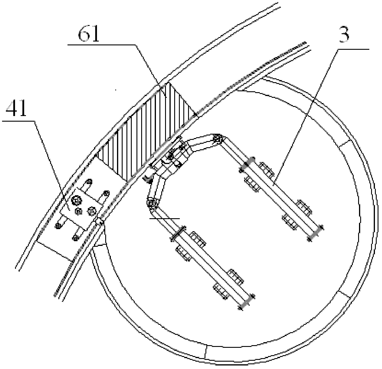
[0029] The annular shield machine of the present invention has an annular shield shell 1 completely different from the conventional circular full-section shield machine, which includes an outer shell 11, an inner shell 12 and a small shield shell 13, the inner shell The shell 12, the small shield shell 13 and the outer shell 11 form an annular cavity. The surrounding formation soil is supported by the outer shell 11, and the assembly of the main pipe piece 61 and the temporary pipe piece 62 is completed under the protection of the outer shell 11;

[0030] The main cutting cutter head 21 is set in the small shield shell 13. Considering the needs of the equipment layout inside the entire shield, the excavation system generally selects muddy water pipelines to discharge the cut soil. The main cutting cutter head 21 must be connected with the inner casing 12 of the annular shield, so that the main pipe piece 61 in the passage can be moved to the position required for the assembly ...


PUM


Abstract

The invention relates to an annular shield machine which comprises a shield housing, a duct piece traction mechanism and a turbid water delivery system, wherein the shield housing comprises an outer housing, an inner housing and a small shield housing; the inner housing, the small shield housing and the outer housing form an annular cavity; small cutting heads are distributed along the circumferential direction of the annular cavity; a primary cutting head is arranged in the small shield housing; the primary cutting head is communicated with the inner housing; and a shield jack is arranged behind the small cutting heads. The invention also provides a tunnel construction method. The annular shield machine disclosed by the invention has the characteristics of safety and reliability, simplicity and convenience, high efficiency, economy, environment friendliness and the like. By using the novel tunnel construction method disclosed by the invention, excavation can be carried out at any tunnel lining part in any shape, then earth and sand are excavated in the constructed tunnel lining, and finally the tunneling is completed.

Description

technical field [0001] The invention relates to a super-large section shield method tunnel construction technology, which belongs to the technical field of building tunnel engineering construction. Background technique [0002] Following the scientific concept of development, our government put forward the requirement of building a resource-saving and environment-friendly society. The key to solving this problem is to use advanced construction equipment and scientific construction technology to fully develop and utilize underground space, transfer urban traffic (subway and rail transit, underground expressway, cross-river and cross-sea tunnels) underground as much as possible, and put everything else Facilities that can be transferred underground (such as parking garages, sewage treatment plants, shopping malls, catering, leisure, entertainment, fitness, etc.) should be built underground as much as possible to achieve multiple land uses, improve land use efficiency, and meet...

Claims


Application Information

Patent Timeline
IPC IPC(8): E21D9/08E21D9/093E21D11/00
Inventor 段创峰王强华魏林春赵燕鹏张露根
Owner SHANGHAI TUNNEL ENG CO LTD
Why Eureka
Try Eureka