Linear displacement sensor

A linear displacement and sensor technology, applied in the direction of instruments, measuring devices, and electric devices, can solve the problems of complex structure, high price, and poor anti-interference ability, and achieve high resolution, low cost, and strong anti-interference ability Effect

Inactive Publication Date: 2012-02-22
CHONGQING UNIV OF TECH
View PDF6 Cites 21 Cited by
  • Summary
  • Abstract
  • Description
  • Claims
  • Application Information

AI Technical Summary

Problems solved by technology

To sum up, the disadvantages of existing grid displacement sensors are: complex structure, high price, poor anti-interference ability

Method used


Image

  • Linear displacement sensor
  • Linear displacement sensor
  • Linear displacement sensor

Examples


Embodiment Construction

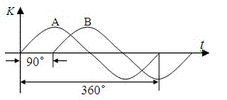
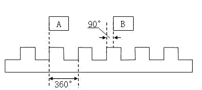
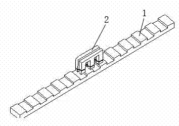
[0020] As shown in Figure 3, Figure 4 , Figure 5 As shown, the sensor is composed of two parts of the substrate, which are divided into a long-scale substrate 1 and a short-scale substrate 2 . Two sets of electromagnetic induction coils composed of exciting coils and induction coils are wound on the base of the short ruler at the same time, and there is a row of magnetizers arranged in equal intervals on the base of the long ruler (that is, the teeth in the figure), on which there are no Winding, that is, in this example, the short ruler is used as the winding ruler, and the long ruler is used as the non-winding ruler. The 2 excitation coils are connected to the 2-phase excitation power supply, and the induction signals are generated on the 2 induction coils, that is, this example takes 2 phases as an example. When the base body of the short ruler and the base body of the long ruler move relative to each other, the amplitude of the induction signal changes due to the chang...


PUM


Abstract

The invention provides a linear displacement sensor, and belongs to the field of accurate displacement measurement. The sensor consists of two substrates, namely a long ruler and a short ruler, wherein an excitation coil and an induction coil are simultaneously wound on one ruler substrate; a row of magnetizers are arranged on the other ruler substrate at equal intervals and are unwound; the excitation coil is connected with an excitation power supply; an induction signal is generated on the induction coil; when the short ruler and the long ruler do relative motion, the amplitude of the induction signal is changed due to the change of magnetic flux; and electric signals output by the excitation coil and the induction coil are connected to a conditioning circuit to be processed, the processed signals are sent to a signal processing circuit to be subjected to amplitude and phase discrimination, an amplitude difference or a phase difference of the signals is expressed by the number of interpolated clock pulses and is converted into a linear displacement value, and the linear displacement value is directly used as linear displacement data to be displayed or output or is subjected to error correction and the like by a microprocessor and a memory and used as the linear displacement data to be displayed or output.

Description

technical field [0001] The invention belongs to the field of displacement precision measurement. Background technique [0002] Linear and angular displacement measurements are the most basic and common measurements. In order to take into account the measurement resolution and range, many displacement sensors adopt a grid structure that is precisely engraved on the substrate, such as a grating, a magnetic grid, etc., and the pulse signals sent by it during the movement are accumulated and counted, that is, the displacement measurement is realized. High-precision and high-density engraved lines cause many problems. On the one hand, the denser the engraved lines, the easier it is to be polluted. No matter how it is sealed and protected, under the harsh working conditions of the production site, its tiny dust and water vapor may contaminate the grid line, making it invalid for counting. On the other hand, the reticle cannot be infinitely dense, and the existing density is far ...

Claims


Application Information

Patent Timeline
Patent Type & Authority Applications(China)
IPC IPC(8): G01B7/02
Inventor 彭东林陈锡侯刘小康杨继森高忠华郑方燕张天恒郑永
Owner CHONGQING UNIV OF TECH
Why Eureka
Try Eureka