Filtering thin film, filtering thin film device and manufacture method thereof
A technology of filter films and filters, which is applied in the direction of filters, optics, optical components, etc., can solve the problems of application limitations, image distortion, large volume and weight of instruments, etc., to improve spectral resolution and occupy space Small and easy to operate
- Summary
- Abstract
- Description
- Claims
- Application Information
AI Technical Summary
Problems solved by technology
Method used
Image

Examples
Embodiment 1
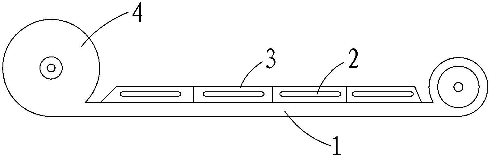
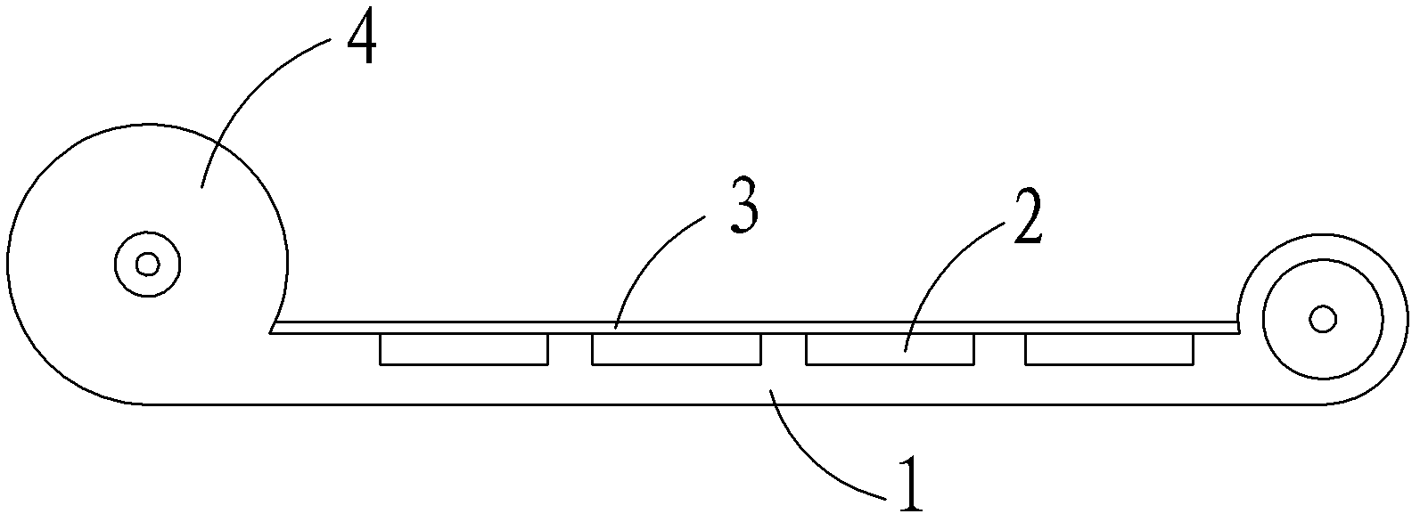
[0031] please join figure 1 , figure 2 , image 3 and Figure 4 , as shown in the figure, the optical filter 2 is stuck on the transparent thin cellophane with an organic resin with good adhesion and strong stress absorption, and the diameter of the transparent thin cellophane is larger than that of the optical filter 2; On the film, according to the design size of the multi-spectral optical filter 2, use a punching machine to make holes; the thin cellophane with the optical filter 2 is bonded to the photographic film or ordinary organic resin with good adhesion and strong stress absorption. On the hole position of the photographic film; the exposed width of the resin ring bonded to the film is 1mm-2mm; the distance between the filters 2 is 2mm-4mm, which does not affect the bonding of adjacent filter 2; mark the filter The magnetic strip medium 5 of the wavelength position identification state of the sheet 2 is glued on the top of the photographic film or ordinary photogr...
Embodiment 2
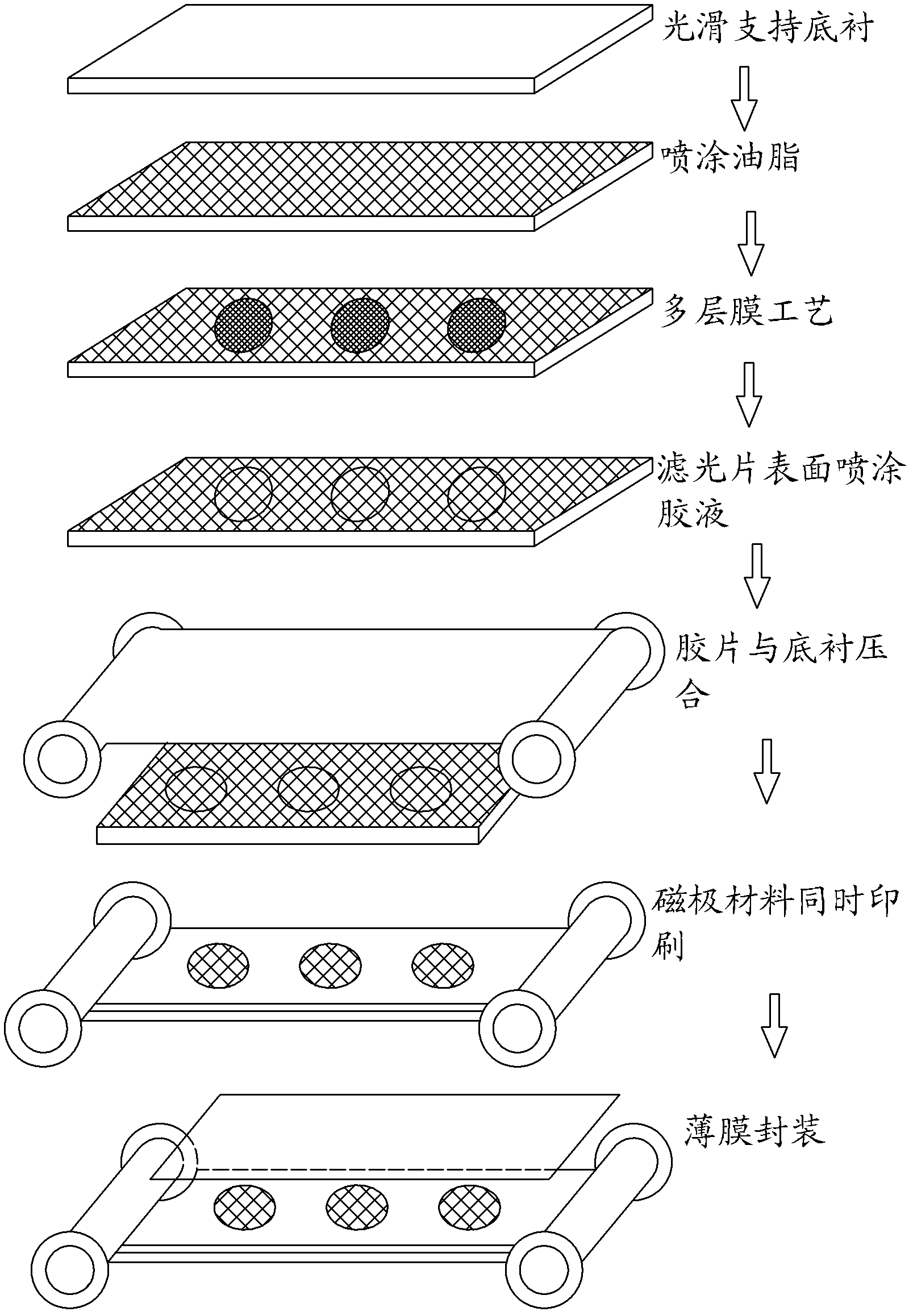
[0036] The present invention adopts the vacuum multi-layer coating technology to coat the optical filters 2 with different transparent bandwidths on the film material. The film material can be photographic film or ordinary photographic film, or optical film medium material. The vacuum multi-layer coating process method is as follows: evenly spray grease on the optical glass, place the filter on the optical glass sprayed with grease, and plate the filter on the optical glass plane coated with grease by using the vacuum multi-layer coating method ;Apply viscose evenly on the position where the filter is placed on the support substrate, the area and shape of the glue are matched with the optical glass plane coated with the filter; the support substrate evenly coated with viscose is placed on the optical glass Press the plane coated with the optical filter; separate the support substrate evenly coated with adhesive from the smooth and hard optical glass, so that the filter is glue...
Embodiment 3
[0038] This embodiment is improved on the basis of embodiment 1, as figure 1 and figure 2 As shown, the embodiment of the filter film device of the present invention includes a filter film and a rotating axle 4 arranged at both ends of the filter film, and the two ends of the filter film are respectively fixed on the corresponding rotating axle 4, and pass through the rotating axle 4 To be unfolded or rolled up, the filter film includes a supporting substrate 1 and at least two optical filters 2 with different transmission bandwidths, and the optical filters 2 are arranged on the supporting substrate 1 in a single row, so that The surface layer of the optical filter 2 is also provided with a transparent protective layer 3 .
[0039] The above-mentioned embodiments and their improvements can be flexibly adjusted according to needs.
PUM
| Property | Measurement | Unit |
|---|---|---|
| Thickness | aaaaa | aaaaa |
Abstract
Description
Claims
Application Information
 - R&D
- Intellectual Property
- Life Sciences
- Materials
- Tech Scout
- Unparalleled Data Quality
- Higher Quality Content
- 60% Fewer Hallucinations
Browse by: Latest US Patents, China's latest patents, Technical Efficacy Thesaurus, Application Domain, Technology Topic, Popular Technical Reports.
© 2025 PatSnap. All rights reserved.Legal|Privacy policy|Modern Slavery Act Transparency Statement|Sitemap|About US| Contact US: help@patsnap.com