Device for measuring current density of arc column of welding arc

A measuring device and technology for current density, applied in welding equipment, arc welding equipment, manufacturing tools, etc., can solve the problems of large error in calculation results, accumulation of errors, and difficulty in arc cross-section, etc., and achieve high accuracy and good insulation effect. , The intuitive effect of the measurement method

Inactive Publication Date: 2012-02-29
XI AN JIAOTONG UNIV
View PDF3 Cites 10 Cited by
  • Summary
  • Abstract
  • Description
  • Claims
  • Application Information

AI Technical Summary

Problems solved by technology

The split anode calculation method has relatively low requirements for high temperature and insulation to a certain extent, but this method is based on the assumption that the arc section is circular. Although it is reasonable to a certain extent, it has poor versatility
And it is difficult to ensure that the arc cross section is circular in actual working conditions
In addition, there is error accumulation, which makes the error of the calculation result large
The probe method can obtain accurate measurement results more intuitively, but it faces two major problems: high temperature (melting the probe) and insulation (between the probe and the anode plate)

Method used


Image

  • Device for measuring current density of arc column of welding arc
  • Device for measuring current density of arc column of welding arc
  • Device for measuring current density of arc column of welding arc

Examples


Embodiment Construction

[0025] The present invention is described in further detail below in conjunction with accompanying drawing:

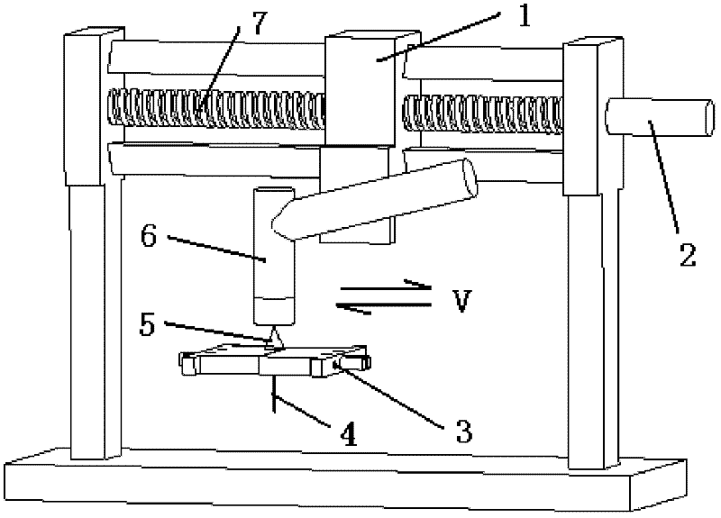
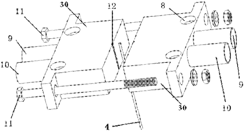
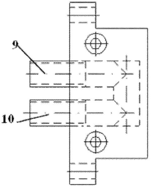
[0026] see Figure 1 to Figure 6 As shown, the welding arc column current density measuring device 3 of the present invention comprises two separated anode plates 30, digs U-shaped holes (cooling water channels) in the two anode plates 30, and passes through the two anode plates 30. Flowing water is used to cool the anode plate 30 and the tungsten probe 4 . At the butt joints of the two anode plates 30, semi-cylindrical grooves 12 are set up respectively, and a layer of Al is sprayed on the inner diameter of the groove 12 by plasma spraying. 2 o 3 Coating for insulation. The tungsten probe 4 is clamped in two grooves 12, and is clamped by two fastening bolts 11 of the copper anode plate 30, so that the tungsten probe 4 can be connected with the Al on the anode plate 30. 2 o 3 Coatings are in close contact to achieve better cooling effect. Leads are drawn from the...


PUM

PropertyMeasurementUnit
thicknessaaaaaaaaaa
radiusaaaaaaaaaa
diameteraaaaaaaaaa

Abstract

The invention discloses a device for measuring the current density of an arc column of a welding arc. The device comprises two anode plates which are separated, wherein cooling water channels are formed in the two anode plates; grooves are formed at the joints of the two anode plates respectively; the inner wall of each groove is provided with an insulating layer; a tungsten probe is clamped in the two grooves of the two anode plates; and a part of the tungsten probe extending out of the lower sides of the anode plates is connected with a current divider through a lead-out lead. In the invention, two water-cooled copper polar plates are provided with semi-cylindrical grooves, Al2O3 plasma coatings are coated in the grooves, the tungsten probe is clamped between the two water-cooled copper polar plates, a lead is connected below the probe, and the probe is connected to a welding power supply after being connected with the current divider; and during measurement, a motor is used for driving a lead screw to rotate, the lead screw is used for driving a slide block and a welding gun to move horizontally, and an electric arc and the probe move relatively, so that the aim of measuring is fulfilled. Due to the adoption of the device, the current density of the arc column of the welding arc can be measured continuously, and the radial distribution condition of the current density along with the arc column of the electric arc can be obtained; and the device has a simple structure and high result accuracy.

Description

【Technical field】 [0001] The invention belongs to the field of physical measurement of welding arc, and in particular relates to a non-melting electrode gas shielded welding arc current density measuring device. 【Background technique】 [0002] Since the emergence of modern welding technology at the end of the 19th century, there has been great progress in both the welding method and the welding process. Because welding has the advantages of convenient forming, strong adaptability, and relatively low cost, it has penetrated into almost all parts of the world. all aspects of industry. With the development of mechanization and automation, today's various industries have put forward higher requirements for welding quality, especially high-tech industries such as aviation, aerospace and national defense. In terms of welding applications, arc welding is dominant, so the research on arc welding has never been interrupted. [0003] Welding arc is a form of gas discharge. As a weld...

Claims


Application Information

Patent Timeline
Patent Type & Authority Applications(China)
IPC IPC(8): B23K9/095B23K9/167
Inventor 殷咸青孙江涛张建勋肖克民苟建军
Owner XI AN JIAOTONG UNIV
Why Eureka
Try Eureka