Abrasive water jet cutting spray head device

An abrasive water jet and water jet technology, applied in abrasives, explosion generating devices, spray guns and other directions, can solve the problems of difficult cleaning, damage to the inner wall of the sand nozzle, easy water return, etc., to improve reliability and processing efficiency, improve work efficiency The effect of reliability and ease of processing

Inactive Publication Date: 2012-02-29
中船西安东仪科工集团有限公司 +1
View PDF7 Cites 30 Cited by
  • Summary
  • Abstract
  • Description
  • Claims
  • Application Information

AI Technical Summary

Problems solved by technology

[0008] The purpose of the present invention is to solve the problem that the negative pressure at the sand inlet of the existing water cutting head and abrasive sand supply device will change due to the sand inlet, causing the water jet to deviate, causing damage to the inner wall of the sand nozzle and affecting cutting. Efficiency issues, easy backwater, difficult to clean, troublesome to use, etc.

Method used


Image

  • Abrasive water jet cutting spray head device
  • Abrasive water jet cutting spray head device

Examples


Embodiment Construction

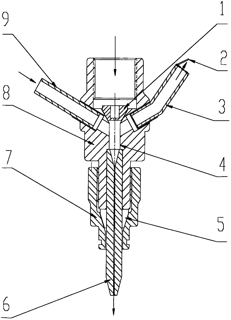
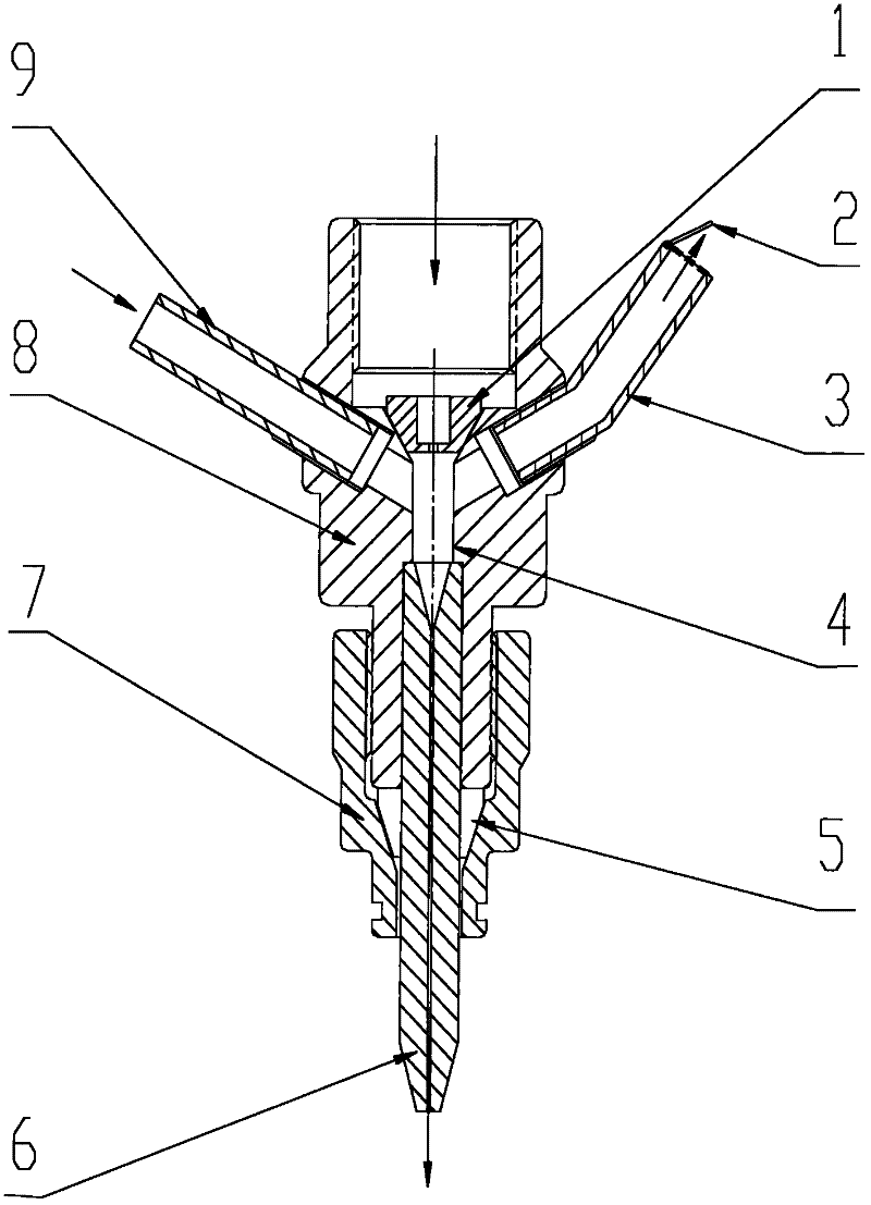
[0014] This embodiment is an abrasive water jet cutting nozzle body, which includes a water jet nozzle 1, a one-way valve cover 2, a cylindrical ring abrasive sand mixing chamber 4, a nozzle body 8, an abrasive sandblasting pipe 6 and an abrasive sand feeding pipe 9. There is a through hole in the center of the nozzle body 8, and one end is a high-pressure water inlet. An abrasive sandblasting tube 6 is installed in the center hole of the other end of the nozzle body 8. The collet 5 is installed at the end of the abrasive blasting tube installation section. And through the compression nut 7, the collet 5, the abrasive blasting pipe 6 and the nozzle body 8 are firmly connected; the water jet nozzle 1 is located in the high-pressure water inlet of the nozzle body. An abrasive sand mixing cavity 4 is formed in the inner hole of the spray head body 8 between the water jet nozzle 1 and the abrasive sandblasting pipe 6 .

[0015] On the shell at the end of the nozzle body 8 with the...


PUM


Abstract

The invention discloses an abrasive water jet cutting spray head device. The center of a spray head body is provided with a through hole, one end of the spray head body is provided with a high-pressure water inlet, an abrasive blasting pipe is arranged in a central hole of the other end of the spray head body, and a spring chuck is arranged at the end of the installation section of the abrasive blasting pipe. A water jet nozzle is positioned in the high-pressure water inlet of the spray head body. An abrasive mixing cavity is formed in an inner hole of the spray head body between the water jet nozzle and the abrasive blasting pipe. The shell of the spray head body is provided with a return water outlet, and the return water outlet corresponds to an abrasive inlet. The included angle between the central line of the return water outlet and the central line of the spray head body is 15 to 30 degrees. The abrasive mixing cavity is formed in the inner hole of the spray head body between the water jet nozzle and the abrasive blasting pipe. By symmetrically and uniformly forming sand inlets and return water holes, the return water produced when the sand blasting pipe 6 is blocked is prevented from entering an abrasive supply valve, and the reliability and the machining efficiency in the cutting process are improved. The device is simple in structure, convenient to machine and easy to implement.

Description

technical field [0001] The invention relates to the field of abrasive water jet cutting, in particular to a water cutting head in an abrasive water jet cutting device. Background technique [0002] High-pressure abrasive water jet cutting technology is developed on the basis of pure water jet cutting technology. It entrains abrasives such as corundum and quartz sand through high-speed water jets, and forms a mixture with water jets in the abrasive mixing chamber. After acceleration, it is sprayed by the abrasive injection tube in the form of mixed flow to form a high-speed abrasive water jet. As we all know, water cutting equipment is widely used in the cutting of various soft and hard materials, and it is more and more widely used. When cutting hard materials such as metal, in order to improve the cutting efficiency, it is necessary to add abrasives such as garnet to the high-pressure water, so that the abrasives can quickly impact the surface of the material to be cut und...

Claims


Application Information

Patent Timeline
Patent Type & Authority Applications(China)
IPC IPC(8): B24C5/04B24C5/00
Inventor 任保林徐合刚陈宇吴英俊张微西李春恒吴继平
Owner 中船西安东仪科工集团有限公司
Why Eureka
Try Eureka