Powder selecting and collecting device

A technology of powder selection and powder pipe, which is applied in chemical instruments and methods, separating solids from solids with airflow, solid separation, etc., can solve the problems of increasing loss along the pipeline, increasing system energy consumption, and powder selection efficiency Influence and other issues, to achieve the effect of improving powder selection and powder collection efficiency, reducing energy consumption, and obvious energy saving effect

Active Publication Date: 2015-03-11
卓卫民
View PDF6 Cites 0 Cited by
  • Summary
  • Abstract
  • Description
  • Claims
  • Application Information

AI Technical Summary

Problems solved by technology

[0009] The technical problem to be solved by the present invention is that the powder selection equipment in the prior art uses the centrifugal principle to select powder and needs to be equipped with a high wind speed, which leads to increased energy consumption of the system, wear and tear on the equipment at the same time, and increases the loss along the pipeline. The centrifugal separation and powder selection of the powder selection equipment are carried out in the same high wind speed environment, which may easily cause the airflow during the centrifugal separation to affect the powder selection settlement, which will affect the powder selection efficiency, and then provide a wind separation with high precision and high air separation efficiency. High-efficiency powder selection and collection device with low energy consumption and little wear on equipment

Method used


Image

  • Powder selecting and collecting device
  • Powder selecting and collecting device
  • Powder selecting and collecting device

Examples


Embodiment 1

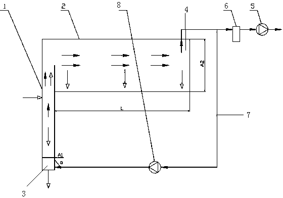
[0047] The device for selecting powder and collecting powder according to the present invention, its structure is shown in figure 1 , it can be seen from the figure that the device includes a powder selection tube 1 and a powder collection tube 2, a feed inlet is set on the upper part of the powder selection tube (as shown by the arrow in the left middle of the powder selection tube in the figure), and a discharge is set at the lower end Inlet and air inlet 3, the powder selection tube 1 is set perpendicular to the horizontal plane, that is to say, the angle α between the axial direction of the powder selection tube 1 and the horizontal plane is equal to 90°; the powder collection tube 2 is set horizontally, the collection The powder pipe 2 communicates with the top of the powder selection pipe 1 and seals the top of the powder selection pipe 1. The powder collection pipe 2 is provided with an outlet at the end far away from the powder selection pipe 1. The air outlet 4 is con...

Embodiment 2

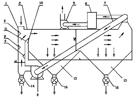
[0054] The device for selecting and collecting powder according to the present invention can also be further provided with one or more guide angles staggered on the inner wall of the powder selecting tube 1 on the basis of the structure of the device described in Embodiment 1, The guide angle is inclined towards the side of the air inlet 3 towards the direction away from the air inlet 3 (see figure 2 shown). As can be seen from the figure, the guide angle 9 is set to an equilateral triangle, and the adjacent two sides between the adjacent guide angles 9 are parallel; as a transformable embodiment, the setting of the guide angle 9 can also be selected as long as it meets The side of the guide angle 9 facing the air inlet 3 can be inclined towards the direction away from the air inlet 3, and the side of the guide angle 9 away from the air inlet can be set to any shape , the white arrow in the figure indicates the flow direction of the powder, and the black arrow indicates the ...

Embodiment 3

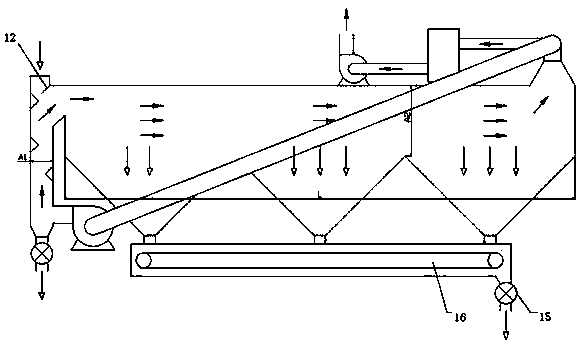
[0058] In the above-mentioned embodiment, the device for selecting powder and collecting powder is directly connected through the connection between the powder selecting pipe 1 and the powder collecting pipe 2; There will be a problem that the material with a low suspension speed will slide into the powder selection tube for repeated winnowing, which will affect the powder selection efficiency. For this reason, the powder selection and powder collection device described in this embodiment is formed with a transition slide section 10 at the connection between the powder selection pipe 1 and the powder collection pipe 2, see image 3 As shown, the white arrow in the figure indicates the flow direction of the powder, and the black arrow indicates the flow direction of the air flow. The top of the transition slide section 10 is a slope 11, and the slope 11 is from one end close to the powder selection tube 1 to close to the One end of the powder collection pipe 2 rises gradually; ...


PUM


Abstract

The invention discloses a powder selecting and collecting device, which comprises a powder selecting pipe and a powder collecting pipe, wherein the upper part of the powder selecting pipe is provided with a feeding hole; the lower end of the powder selecting pipe is provided with a discharging hole; the powder selecting pipe and the powder collecting pipe are communicated with each other; the powder selecting pipe is arranged obliquely to the horizontal surface; the included angle alpha between the powder selecting pipe and the horizontal surface is more than or equal to 45 degrees and less than or equal to 90 degrees; the powder collecting pipe is arranged horizontally; the lower end of the powder selecting pipe is provided with an air inlet; the powder collecting pipe is provided with an air outlet far away from one end which is communicated with the powder selecting pipe; and the air outlet is connected with a draught fan. In the device, high air speed required by a powder selecting process of a centrifugal separating technology is not required, the aims of selecting powder and subsequently collecting powder can be fulfilled by setting the air speed at 2 meters per second in the powder selecting pipe, and the energy consumption is lowered; mostly importantly, powder selection and powder collection are performed in the powder selecting pipe and the powder collecting pipe which are communicated with each other but are not interfered with each other, so that the influence of airstream flow during centrifugal separation on powder collection is avoided, and the powder selecting and powder collecting efficiencies are increased; and the overall pressure loss of the device does not surpass 100 Pa which is only 5-10 percent of the pressure loss of the conventional centrifugal separation powder selecting system, and the energy-saving effect is remarkable.

Description

technical field [0001] The invention relates to a gas-solid separation device, in particular to a device for selecting and collecting powder. Background technique [0002] Industrial powder separation is a common process in the modern industrial production process. It is widely used in metallurgy, chemical industry, cement, food and other industries. In the cement industry alone, raw materials, clinker and raw coal are ground, and the annual powder selection can reach nearly 5 billion tons, for such a huge amount of powder selection, more than 60% of the electric energy in the cement production process is consumed in the powder making and powder selection process. [0003] At present, powder separators are widely used in powder manufacturing industries such as cement production. So far, the development of powder separator has gone through the following three generations: [0004] The first generation of powder separator, that is, centrifugal powder separator, was invented ...

Claims


Application Information

Patent Timeline
Patent Type & Authority Patents(China)
IPC IPC(8): B07B7/01B01D45/02
Inventor 卓卫民
Owner 卓卫民
Why Eureka
Try Eureka