
Dragging length-measuring thin plate hydraulic cutter

A technology of hydraulic shearing and thin plate, applied in shearing device, shearing machine equipment, measuring/indicating equipment, etc., can solve the problems of poor shearing quality, many equipment failures, and less equipment functions, and achieves the improvement of belt threading speed and shearing speed. The effect of cutting speed, narrow space and compact design structure

Inactive Publication Date: 2012-03-07
XINJIANG BAYI IRON & STEEL
View PDF13 Cites 4 Cited by
  • Summary
  • Abstract
  • Description
  • Claims
  • Application Information

AI Technical Summary

Problems solved by technology

[0002] The original design of the exit of the cold tandem rolling unit in some rolling mills only has steering rollers. The cutting of the head and tail of the strip and the sectioning of the middle stop are manually cut, which is labor-intensive and unsafe. Due to the narrow space, standard hydraulic shears cannot be used.
After improvement, the steering roll was changed to hydraulic shears. Although it has been improved, there are many equipment failures, poor shearing quality, and the length and speed of the rolled strip cannot be accurately measured. The equipment has few functions, which affects the strip threading speed. Shear speed and production safety

Method used


Image

  • Dragging length-measuring thin plate hydraulic cutter
  • Dragging length-measuring thin plate hydraulic cutter
  • Dragging length-measuring thin plate hydraulic cutter

Examples


Embodiment Construction

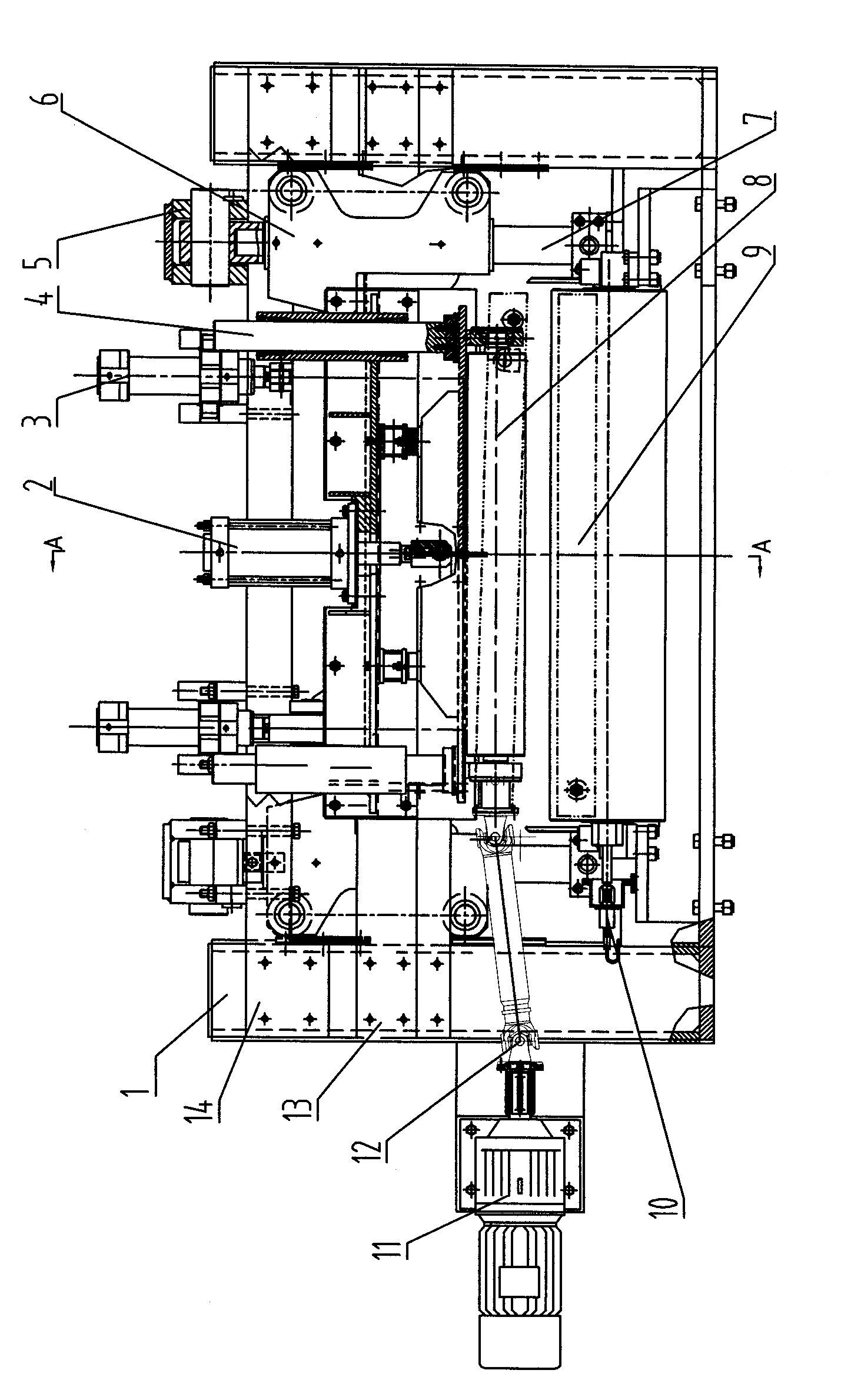
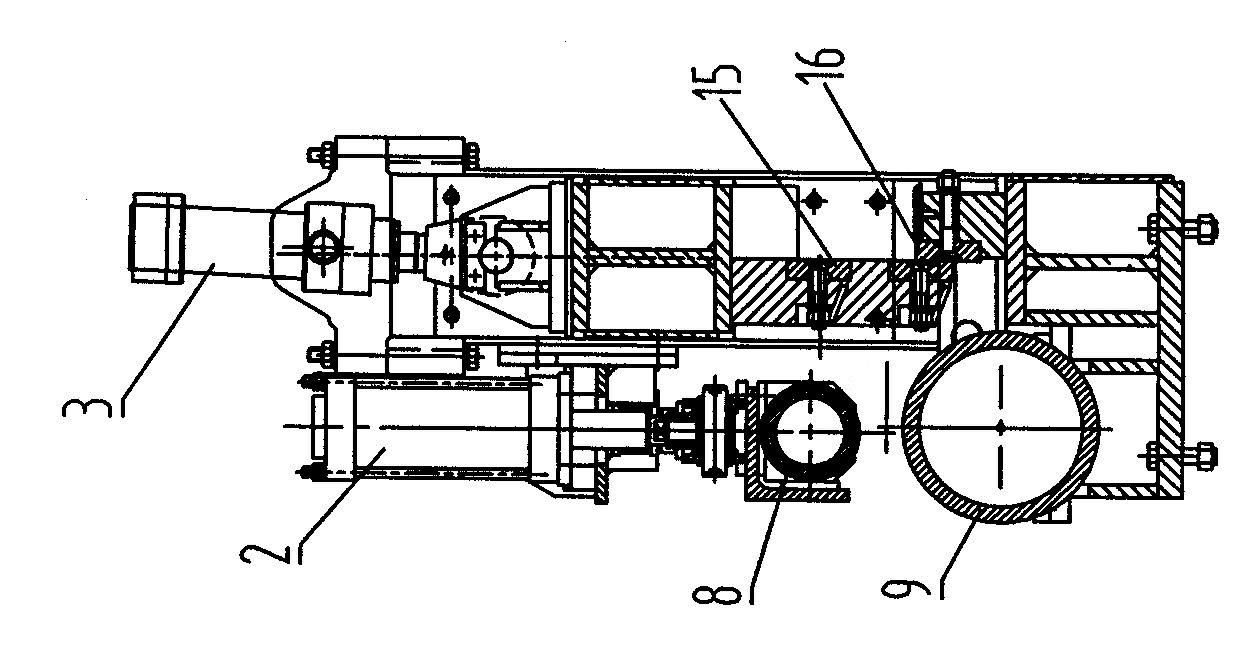
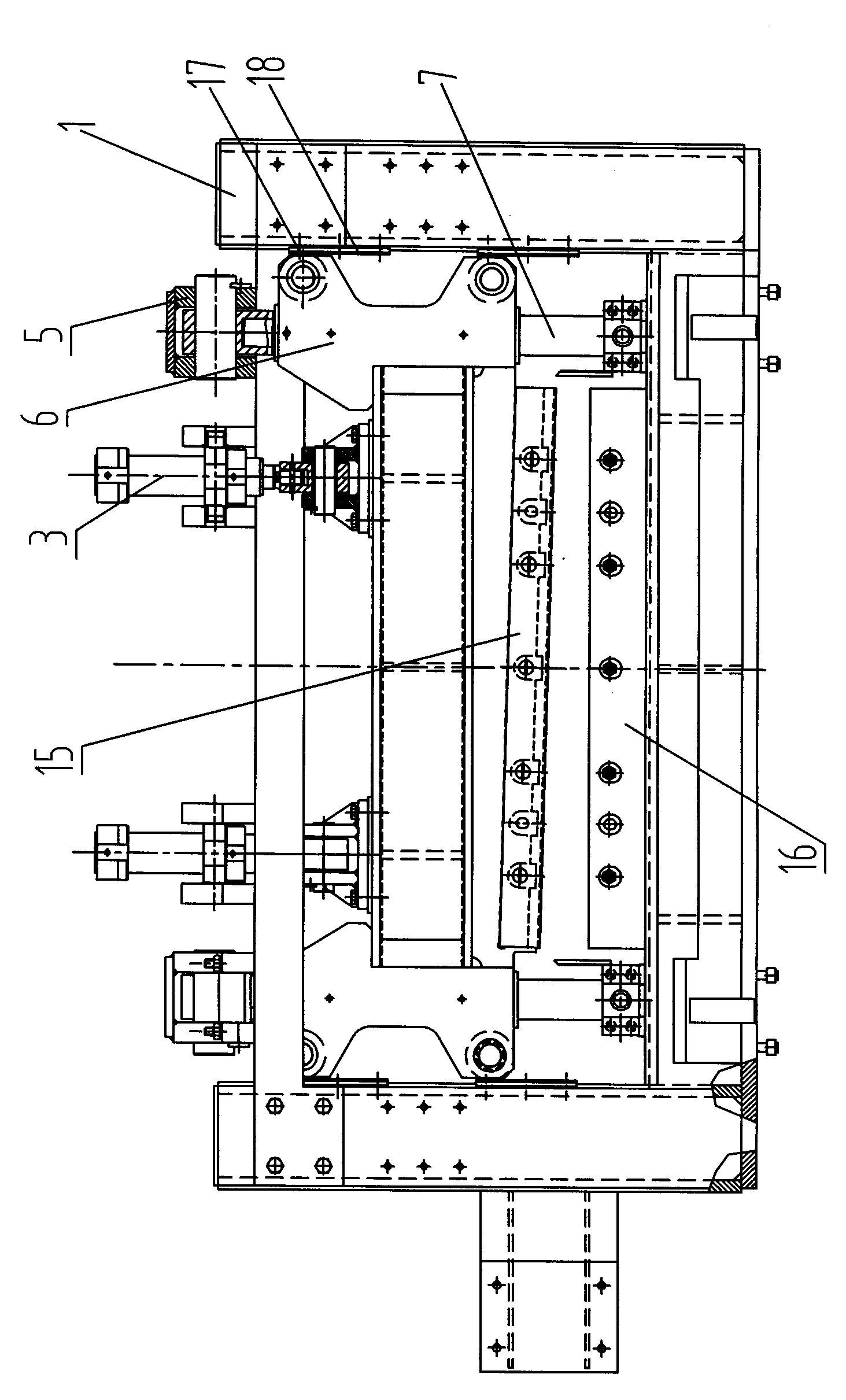
[0013] A hydraulic shear for dragging and measuring thin plates, such as figure 1 , figure 2 , image 3 , Figure 4 As shown, the upper shearing edge 15 driven by the hydraulic cylinder 3 is installed through the portal frame, the upper shearing edge 15 is matched with the lower shearing edge 16 installed on the machine base, and the upper beam 14 is fixed on the open door frame 1 by bolts. Above, a symmetrical hinged seat 5 is arranged on the upper beam 14, the upper end of the guide post 7 is hinged with the hinged seat 5, the lower end of the guide post 7 is respectively connected to the frame by adjusting bolts, and the two sides of the upper shearing edge 15 are fixed to the symmetrical The guide frame 6, the guide sleeve provided on the guide frame 6 and the guide column 7 are dynamically matched, the roller 17 arranged outside the guide frame 6 is matched with the liner plate 18 arranged inside the open door frame 1, and the suspension beam 13 is fixedly connected by...


PUM


Abstract

The invention discloses a dragging length-measuring thin plate hydraulic cutter. An upper cross beam is fixed on an open door frame, a hinge seat is arranged on the upper cross beam, the upper end of a guide post is hinged with the hinge seat, the lower end of the guide post is respectively connected on a baseframe, symmetric guide frames are fixedly connected on the two sides of an upper cutting blade, guide sleeves arranged on the guide frames are in movable fit with the guide post, idler wheels of the guide frames are matched with a lining plate of the open door frame, a suspension beam is fixedly connected onto the open door frame, a cylinder and the guide sleeves in fit with the guide post are all fixed on the suspension beam, the end part of a piston rod of the cylinder and the lower end of the guide post are connected with a movable base plate, a rubber roller is mounted on the back surface of the movable base plate, a motor drives the rubber roller to rotate, a built-in bearing and an encoder connecting rod structure are arranged, and a free roller matched with the rubber roller is arranged on the baseframe. The dragging length-measuring thin plate hydraulic cutter disclosed by the invention has multiple using functions and has the advantages of flattening strip steel, centring, dragging and auxiliary strip penetrating, cutting head, tail and middle part of the strip steel, cutting and shunt winding, accurately measuring length and speed of the rolled strip steel and the like, improving strip penetrating speed and cutting speed, ensuring production safety and improving production efficiency.

Description

technical field [0001] The invention belongs to equipment for dragging and cutting to length for cold-rolled or hot-rolled coils in a steel rolling mill, in particular to dragging and length-measuring sheet hydraulic shears. Background technique [0002] The original design of the exit of the cold tandem rolling unit in some rolling mills is only the steering roll. The cutting of the head and tail of the strip and the sectioning of the middle stop are manually cut, which is labor-intensive and unsafe. Due to the narrow space, standard hydraulic shears cannot be used. After improvement, the steering roller was changed to hydraulic shears. Although it has been improved, there are many equipment failures, poor shearing quality, and the length and speed of the rolled strip cannot be accurately measured. The equipment has few functions, which affects the strip threading speed. Shear speed and production safety. Contents of the invention [0003] The object of the present inven...

Claims


Application Information

Patent Timeline
IPC IPC(8): B23D15/14B23D15/08B23D33/02B23Q17/20
Inventor 李子文肖国栋王国义
Owner XINJIANG BAYI IRON & STEEL
Learn More