Rotary clamp for lathe
A rotary and lathe technology, applied in the direction of clamping, manufacturing tools, supports, etc., can solve the problems of overall workpiece quality decline, lower work efficiency, inconsistent precision, etc., to eliminate the influence of centrifugal force, improve work efficiency, and improve dimensional accuracy Effect
- Summary
- Abstract
- Description
- Claims
- Application Information
AI Technical Summary
Problems solved by technology
Method used
Image

Examples
Embodiment Construction
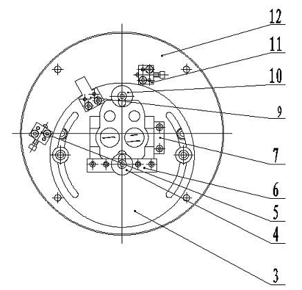
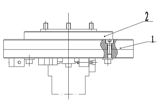
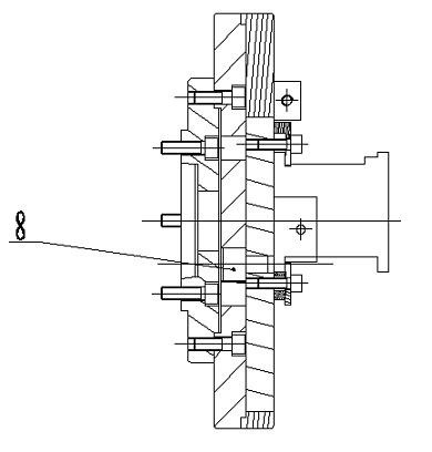
[0013] Such as figure 1 , figure 2 and image 3 As shown, the fixture for a rotary lathe includes an intermediate plate 1, a connecting plate 2, a rotating plate 3, a pressure plate 4, a block 5, a positioning plate 6, a positioning plate 2 7, a connecting shaft 8, a positioning block 9, and a pressure plate Two 10, block two 11 and motherboard 12, the intermediate disk 1 is fixedly connected with the connection disk 2, the connection disk 2 is fixed on the main shaft of the lathe, the rotating plate 3 is arranged at the gap of the motherboard 12 and connected to the intermediate disk 1, The big end of the connecting shaft 8 is set in the middle disc hole, the small end is connected with the rotating plate, the motherboard 12 is reversely connected and fixed on the middle disc 1, the stopper 5, the positioning plate 1 6, the positioning plate 2 7, the positioning block 9 and pressure plate 2 10 are fixed on the rotating plate 3, the stopper 5 and the pressure plate 2 10 are...
PUM
 Abstract
Description
Claims
Application Information
 - Generate Ideas
- Intellectual Property
- Life Sciences
- Materials
- Tech Scout
- Unparalleled Data Quality
- Higher Quality Content
- 60% Fewer Hallucinations
Browse by: Latest US Patents, China's latest patents, Technical Efficacy Thesaurus, Application Domain, Technology Topic, Popular Technical Reports.
© 2025 PatSnap. All rights reserved.Legal|Privacy policy|Modern Slavery Act Transparency Statement|Sitemap|About US| Contact US: help@patsnap.com