
Fuse salt jet impinging heat dump

A technology of jet impact and molten salt, which is applied in the field of molten salt heat absorbers, can solve the problems of heat absorption surface ablation thermal stress, uneven heat flux density, low heat transfer coefficient, etc., solve the problem of antifreeze and thawing, and reduce heat absorption The effect of simple area and manufacturing process

Inactive Publication Date: 2012-03-07
INST OF ELECTRICAL ENG CHINESE ACAD OF SCI
View PDF7 Cites 10 Cited by
  • Summary
  • Abstract
  • Description
  • Claims
  • Application Information

AI Technical Summary

Problems solved by technology

[0006] 1. To overcome the problems of ablation of the heat-absorbing surface and thermal stress damage caused by the uneven heat flux density of the heat-absorbing surface of the traditional heat-absorbing pipe;
[0007] 2. To overcome the problem of low convective heat transfer coefficient of the pipeline fluid medium in the heat absorber;
[0008] 3. Solve the problem of antifreeze and thawing of molten salt in pipelines in traditional molten salt heat absorbers

Method used


Image

  • Fuse salt jet impinging heat dump
  • Fuse salt jet impinging heat dump
  • Fuse salt jet impinging heat dump

Examples


specific Embodiment

[0037] There are two specific embodiments of the molten salt jet impinging the heat absorber 8 of the present invention: Example 1, the molten salt jet impinging on the cavity heat sink 19; Example 2, the molten salt jet impinging on the cylindrical heat sink 20.

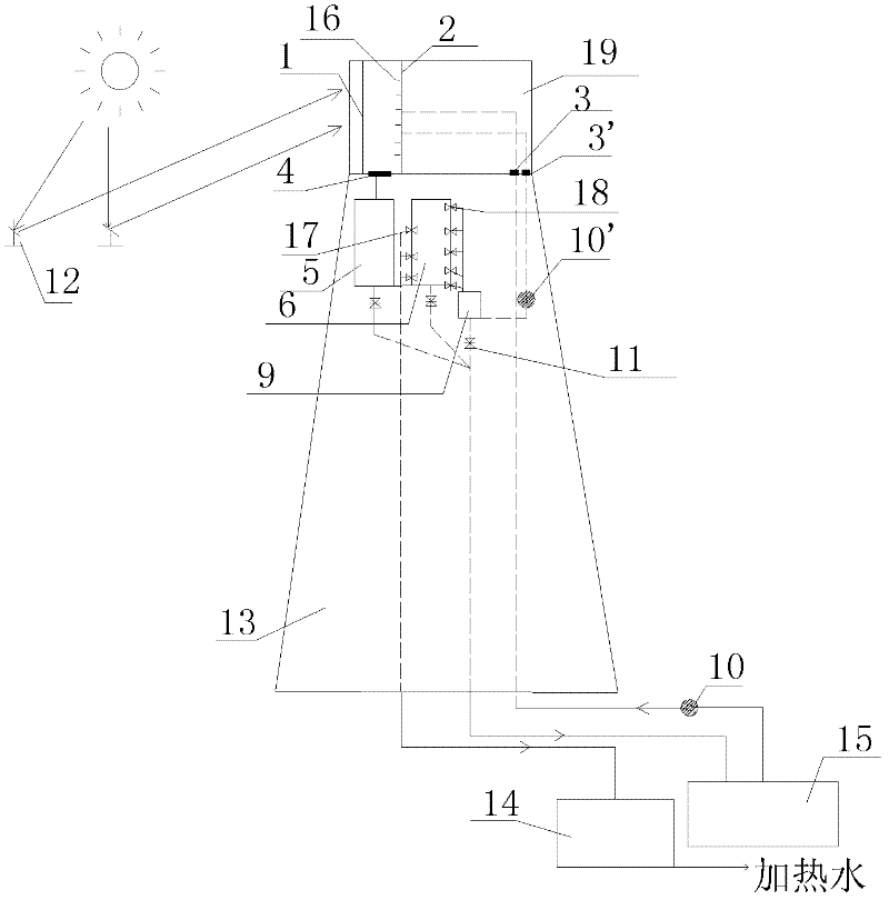
[0038] figure 1 It is a schematic diagram of the structure of a solar power station equipped with the molten salt jet impingement cavity heat absorber of the present invention. Such as figure 1 As shown: the molten salt jet impacting cavity heat sink 19 is located on the top of the solar tower 13, which can be perpendicular to the ground or have a certain angle with the ground. There are two inlets at the bottom of the molten salt jet impingement cavity heat absorber 19. The inlet of the first inlet 3 is connected to the cold tank 15 through the pipe through the pump 10, and the outlet of the first inlet 3 is connected to the cold tank 15 through the pipe connection. The inlet of the nozzle 16 on the high temperature s...


PUM


Abstract

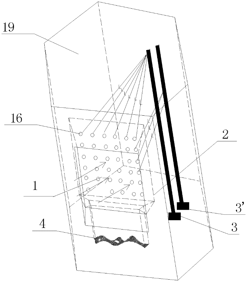
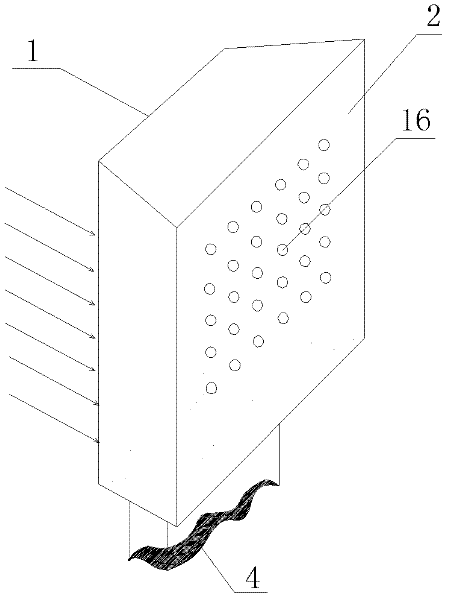
The invention relates to a fuse salt jet impinging heat dump which comprises an absorber (1), a high-temperature steel plate (2), inflow ports (3 and 3'), an outlet (4) and a nozzle (16), wherein the fuse salt jet impinging heat dump (8) is a of cylinder shape, and the front of the absorber (1) faces converged sunlight; the high-temperature steel plate (2) is positioned at the interior of the fuse salt jet impinging heat dump (8) and fixed on the shell of the fuse salt jet impinging heat dump (8) in welding manner, and the high-temperature steel plate (2) is embedded with the nozzle (16); an outlet of the nozzle (16) faces the back of the absorber (1), the inlet is connected with the inflow ports (3 and 3') arranged on the bottom of the fuse salt jet impinging heat dump (8); fuse salt is delivered to the inflow ports (3 and 3') through pump exhausting to flow to the nozzle (16) through a pipeline, thereby spraying to absorber (1), and the absorber (1) is subjected to jet impinging cooling so as to take away the heat; and the heated fuse salt flows out from the outlet (4) of bottom of a gap positioned between the absorber (1) and high-temperature steel plate (2).

Description

Technical field [0001] The invention relates to a molten salt heat absorber for solar tower thermal power generation. Background technique [0002] Solar thermal power generation has attracted much attention in the field of new energy due to its unlimited resources and pollution-free. Among them, the tower-type solar thermal power generation technology has attracted a large number of scientific researchers for its huge commercial prospects. The heat absorber is a key component of solar tower thermal power generation. The molten salt heat absorber has attracted great attention from researchers due to the many advantages of molten salt working fluid and has been used in Solar Two and Solar Tres power stations. [0003] At present, the heat absorbers that use fluid as the heat transfer medium include cavity type and cylindrical type. US Patent No. 5,862,800 describes a cylindrical heat sink that uses molten salt as a working fluid. The heat-absorbing surface of the heat sink is made...

Claims


Application Information

Patent Timeline
Patent Type & Authority Applications(China)
IPC IPC(8): F24J2/04F24J2/46F24J2/48
CPCY02E10/44
Inventor 李鑫廖志荣王志峰
Owner INST OF ELECTRICAL ENG CHINESE ACAD OF SCI
Learn More