System for in-situ mixing and diluting fluorine gas

A technology of fluorine gas and gas supply, which is applied in the field of on-site gas mixing and dilution systems of fluorine gas, which can solve the problems of difficult homogenization of mixed gas, increased homogenization time, and decreased productivity.

Inactive Publication Date: 2012-03-07
CENT GLASS CO LTD
View PDF7 Cites 16 Cited by
  • Summary
  • Abstract
  • Description
  • Claims
  • Application Information

AI Technical Summary

Problems solved by technology

[0013] When the mixed gas is stored using a large buffer tank capable of supplying a large amount of gas, it becomes difficult to homogenize the mixed gas as the tank becomes larger
The mixed gas can be homogenized just by leaving it for a long time, but in the conventional method, the time required for each component of the mixed gas to be homogenized increases with the size of the container, which has the problem of lowering productivity.

Method used


Image

  • System for in-situ mixing and diluting fluorine gas
  • System for in-situ mixing and diluting fluorine gas
  • System for in-situ mixing and diluting fluorine gas

Examples


Embodiment Construction

[0023] Next, an example of a preferred embodiment of the present invention will be described using the drawings.

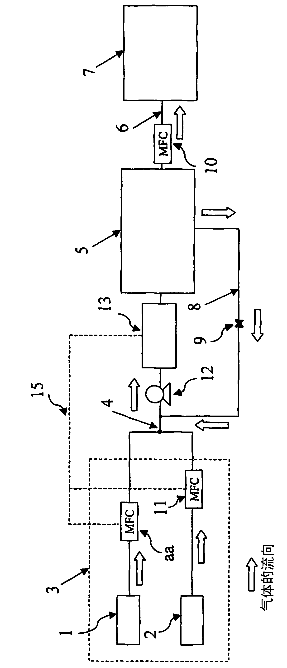
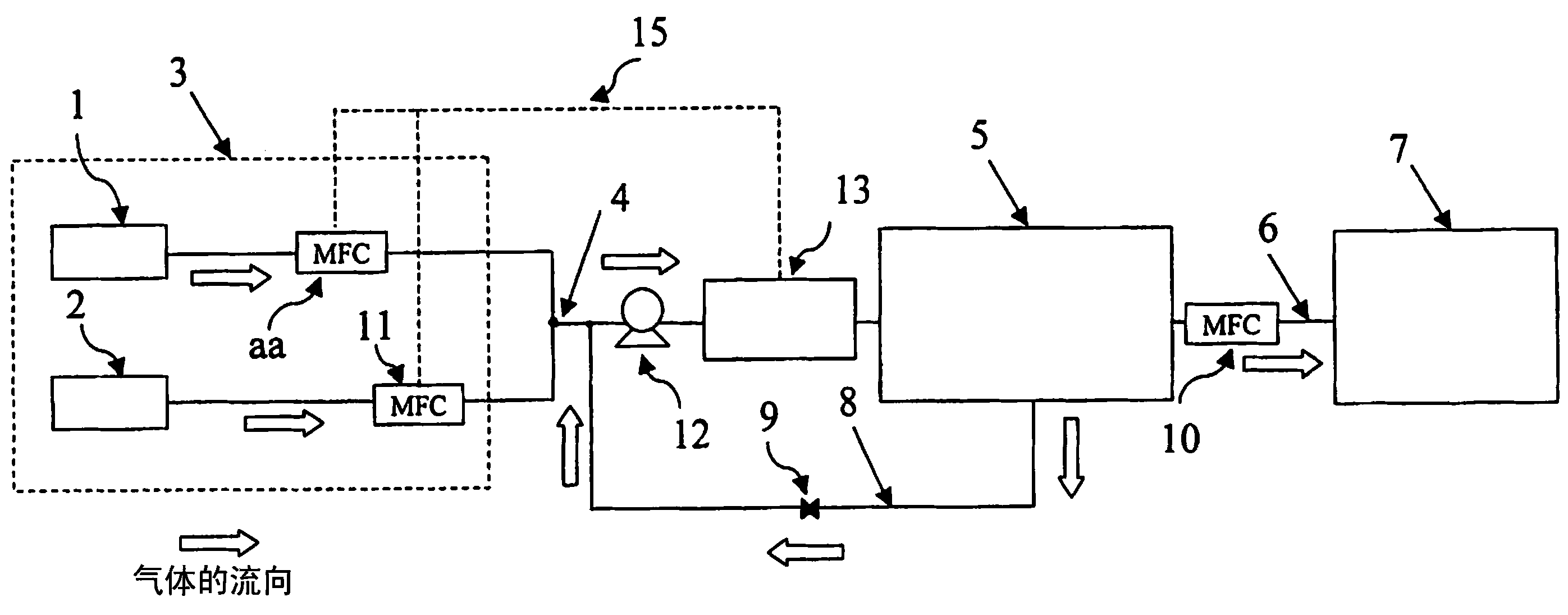
[0024] figure 1 It is a schematic diagram showing a fluorine gas supply system to which the present invention is applied.

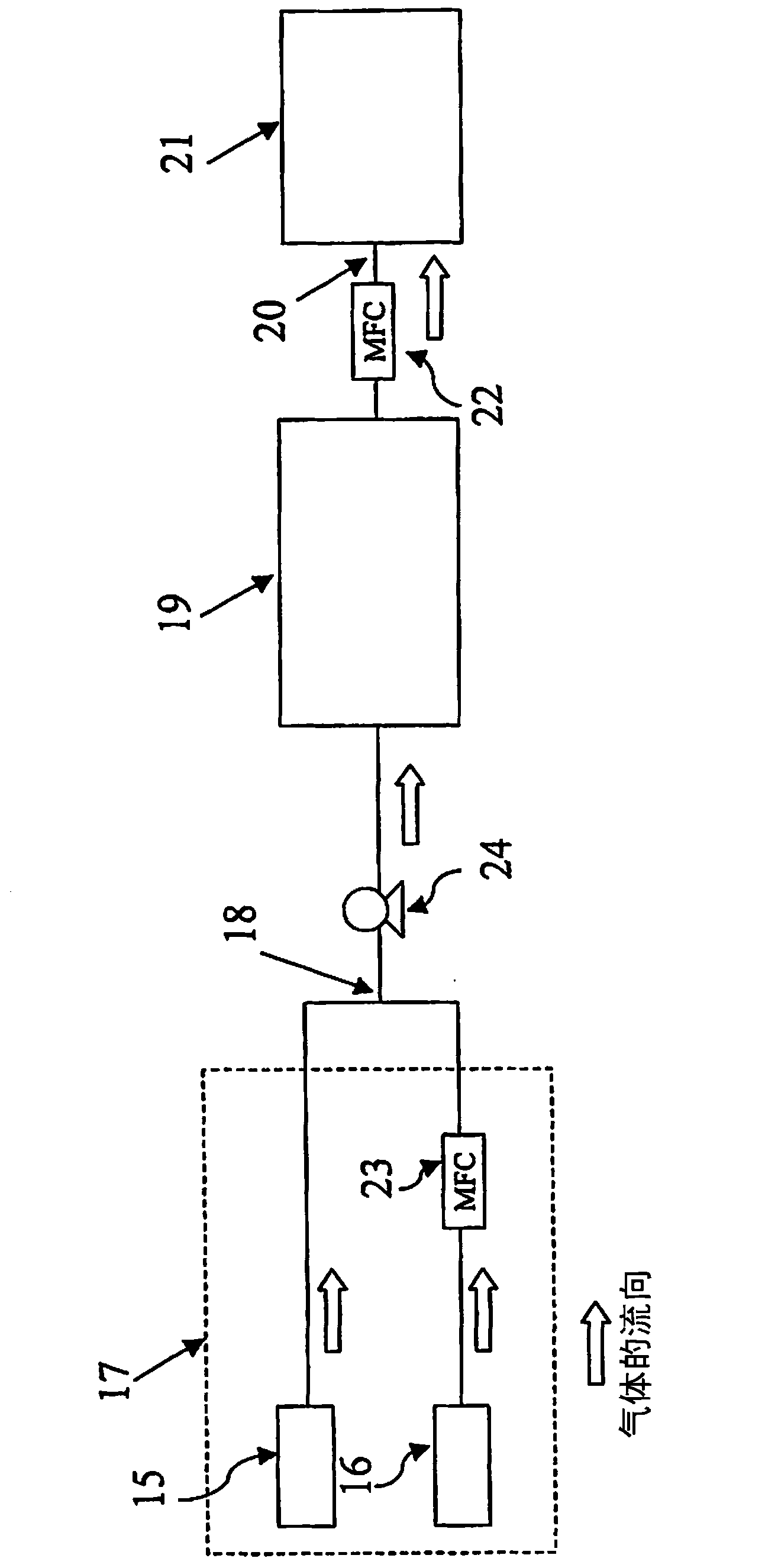
[0025] figure 2 It is a schematic diagram showing a comparative example using a fluorine gas supply system as compared with the present invention.

[0026] Fluorine gas supply system of the present invention

[0027] first of all, yes figure 1 The fluorine gas supply system of the present invention shown will be described.

[0028] figure 1 The shown fluorine gas supply system mixes fluorine gas obtained from a fluorine gas generator with an inert gas for adjusting the fluorine gas to a specified concentration, stores the mixed gas in a buffer tank, and supplies the mixed gas to the target The gas supply system of the semiconductor processing device of the device is characterized in that the mixed gas stored in the buffer tank is int...


PUM


Abstract

It is a task to provide a fluorine gas supply system which can stably supply fluorine gas generated by a fluorine gas generation device to a semiconductor processing device in a large quantity and in a precise concentration. In the fluorine gas supply system, a mixed gas stored in a buffer tank is introduced into a gas introducing piping before the mixed gas is adjusted in the buffer tank to circulate the mixed gas and a monitoring device is disposed which measures a fluorine gas concentration within the mixed gas so that, in response to the obtained fluorine gas concentration, a flow quantity of inert gas supply source can be adjusted.

Description

technical field [0001] The present invention relates to a fluorine gas supply system located between an on-site fluorine gas generator and a semiconductor processing device using fluorine gas, that is, an in-situ gas mixing and dilution system for fluorine gas. Background technique [0002] At present, in the cleaning and etching process of semiconductor processing, electronic material gases (such as fluorocarbons, sulfur hexafluoride gas, nitrogen trifluoride and other fluoride gases) have shown high performance, so they have been widely used in a large range The above-mentioned gases are used, but these fluoride gases have a large greenhouse effect coefficient and cause adverse effects on the global environment. Therefore, it is decided to abolish or restrict the use of the above-mentioned gases in the future. [0003] Since the greenhouse effect coefficient of fluorine gas is zero, researches on the use of fluorine gas as a substitute for the above-mentioned fluoride gase...

Claims


Application Information

Patent Timeline
Patent Type & Authority Applications(China)
IPC IPC(8): H01L21/3065H01L21/205C01B7/20B01F23/10
CPCC01B7/20G05D11/132B01F23/191B01F35/82H01L21/3065H01L21/205
Inventor 菊池亚纪应毛利勇八尾章史宫崎达夫中原启太
Owner CENT GLASS CO LTD
Why Eureka
Try Eureka