Yarn heating apparatus

A heating device and silk thread technology, which is applied in the direction of artificial filament heat treatment, artificial filament physical therapy, and complete sets of equipment for the production of artificial threads, etc., can solve the problems of increased warm air volume, increased heater power consumption, etc., and achieve temperature suppression Effects of reducing, reducing power consumption, and suppressing temperature drop

Active Publication Date: 2012-03-14
TMT MACHINERY INC
View PDF11 Cites 19 Cited by
  • Summary
  • Abstract
  • Description
  • Claims
  • Application Information

AI Technical Summary

Problems solved by technology

In addition, when the inflow of cold air into the above-mentioned internal space or the outflow of warm air from the above-mentioned internal space occurs, the temperature of the above-mentioned internal space drops, so the power consumption of the heater required to heat the yarn to an appropriate temperature increase
[...

Method used


Image

  • Yarn heating apparatus
  • Yarn heating apparatus
  • Yarn heating apparatus

Examples


Embodiment Construction

[0062] A preferred first embodiment of the present invention will be described below.

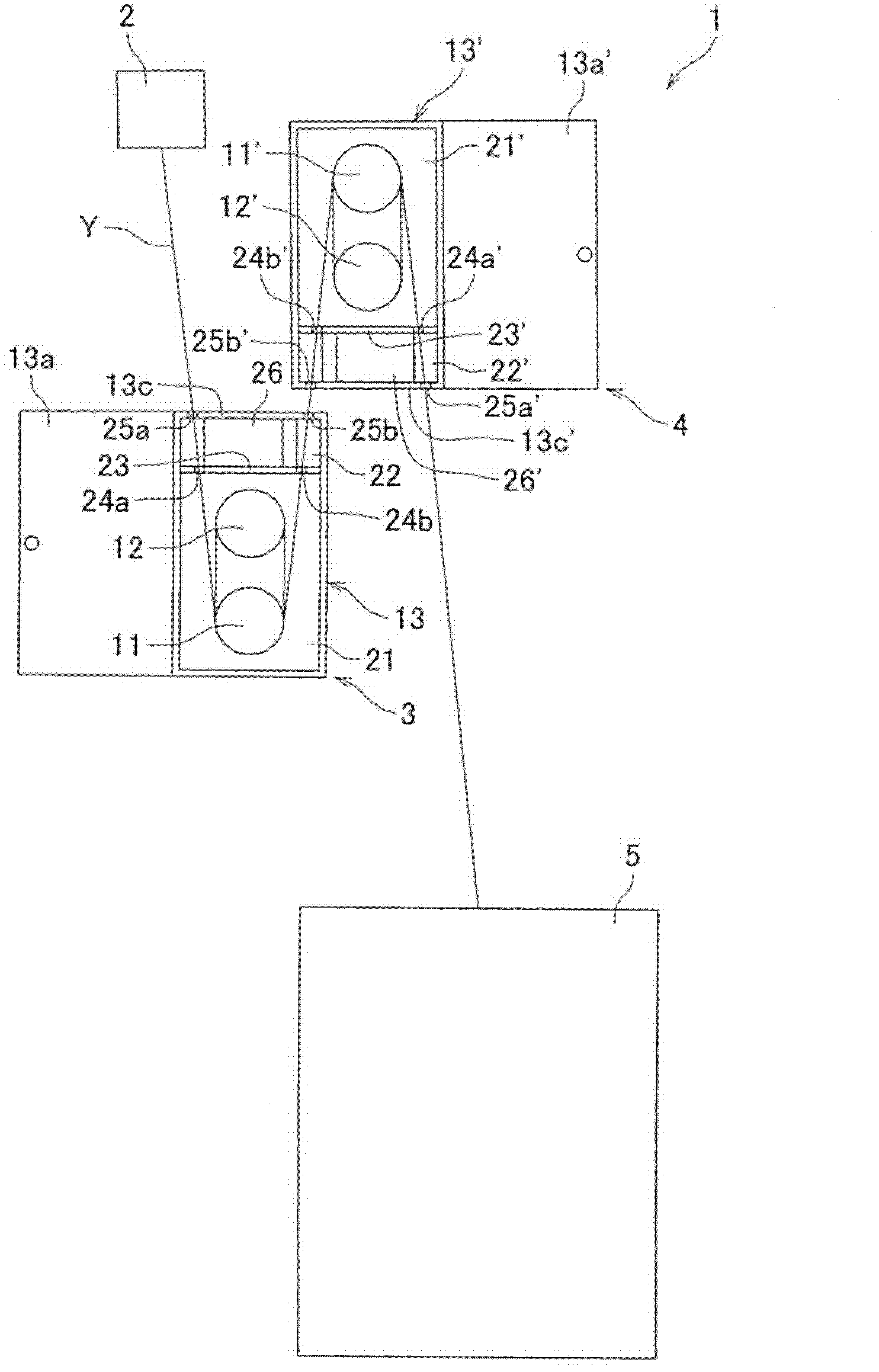
[0063] Such as figure 1 As shown, the yarn manufacturing apparatus 1 includes a spinning machine 2 , two roll units 3 and 4 (yarn heating devices), and a winder 5 . The spinning machine 2 makes a plurality of (for example, about 24 to 32) yarns Y along the figure 1 It is spun downward in a state where the drawing surfaces are aligned in the vertical direction. The roller units 3 , 4 heat and stretch the plurality of yarns Y spun from the spinning machine 2 . The winder 5 winds the plurality of yarns Y stretched by the roller units 3 and 4 onto a bobbin (not shown).

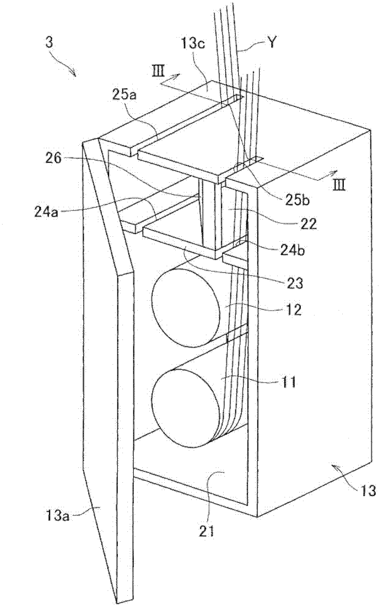
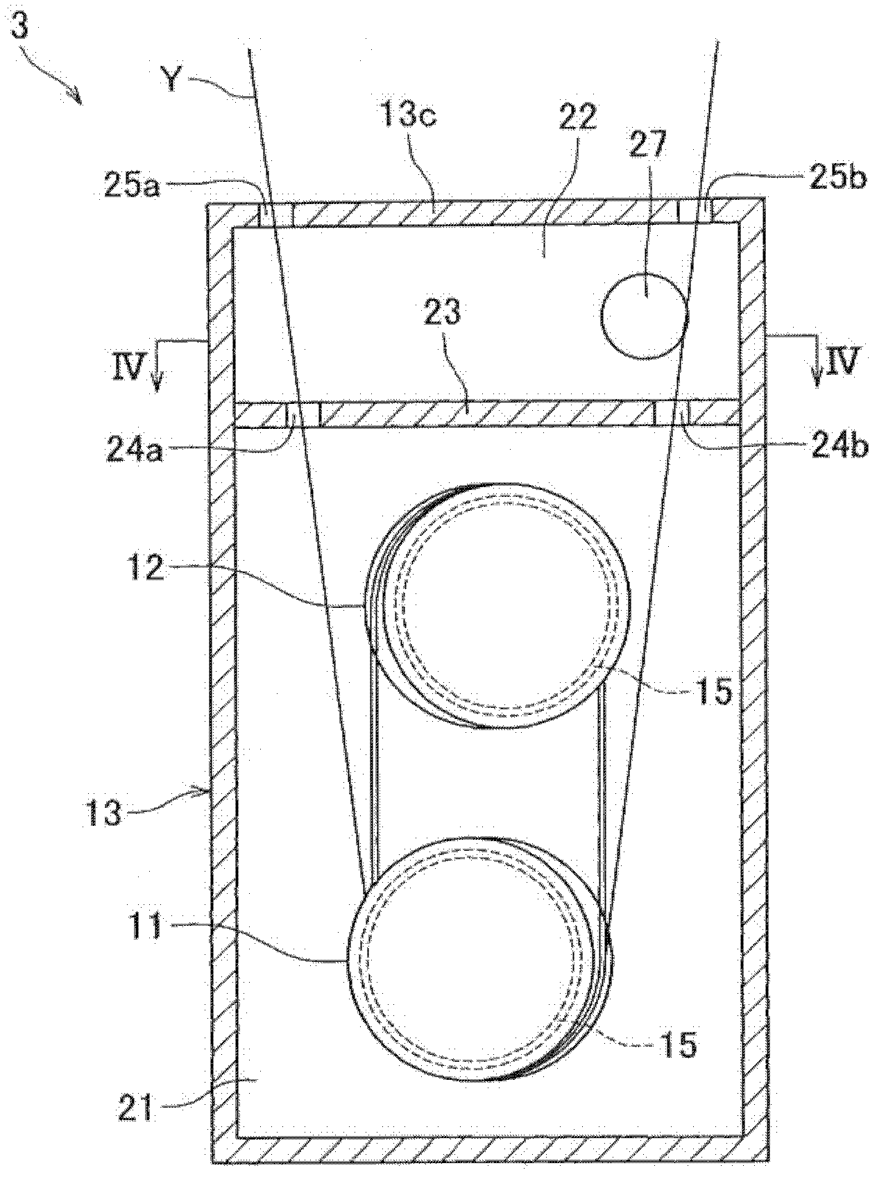
[0064] In addition, since the structure of the spinning machine 2 and the winding machine 5 in the above-mentioned structure of the yarn manufacturing apparatus 1 are the same as those of the prior art, detailed description thereof will be omitted, and the roll units 3 and 4 will be described in detail below.

[0065] Such ...


PUM


Abstract

The invention provides a yarn heating apparatus with a reduced power consumption for heating yarns fed by a yarn feeding roller. In a thermal insulation box (13), above a thermal insulation space (21) in which a godet roller (11) and a separate roller (12) each having a heater (15) are provided, a connecting space (22) separated from a thermal insulation space by a wall (23) is provided. Yarns (Y) spun out from a spinning machine enter the thermal insulation space after passing through a slit (25a) at an upper wall (13b) of the thermal insulation box (13), the connecting space, and a slit (24a) on the wall, reciprocate between the rollers (11) and (12) plural times, and then go out from the thermal insulation space to the outside of the thermal insulation box through a slit (24b) of the wall (23), the connecting space, and a slit (25b) of the upper wall (13b). In so doing, an accompanied flow generated around the running yarns (Y) causes a part of air having flown out from the thermal insulation space through the slit (24b) to return to the thermal insulation space through the connecting space and the slit (24a).

Description

technical field [0001] The present invention relates to a wire heating device for heating a wire. Background technique [0002] Patent Document 1 describes a technique in which a plurality of yarns spun from a spinning machine are heated and stretched in two roll units, and then wound up in a winder (winder). In more detail, a plurality of yarns spun from a spinning machine are wound multiple times between godet rolls and separation rolls in each roll unit, and are guided while being conveyed multiple times between these rolls. The rollers are heated. Then, the heated yarn is stretched between two godet rolls constituting two roll units. [0003] In addition, the godet roll and separation roll of each roll unit are accommodated in the inner space (insulation space) of the box (insulation box), so that the heat generated by the heater of the godet roller does not easily escape from the inner space to the outside. Moreover, two slits are formed on the outer wall of the box ...

Claims


Application Information

Patent Timeline
IPC IPC(8): D02J13/00
CPCD02J13/005D01D5/16D01D10/02D01D10/0436D01D13/02D01H13/28D02J1/22
Inventor 石丸德希
Owner TMT MACHINERY INC
Why Eureka
Try Eureka