
Forming method of metal-oxide semiconductor (MOS) transistor source drain stress area and manufacturing method of MOS transistor

A technology of MOS transistors and manufacturing methods, applied in semiconductor/solid-state device manufacturing, electrical components, circuits, etc., can solve problems affecting the energy band structure of the channel region, affecting carrier mobility, etc., and achieve the effect of reducing the difficulty of formation

Inactive Publication Date: 2012-03-14
INST OF MICROELECTRONICS CHINESE ACAD OF SCI
View PDF8 Cites 8 Cited by
  • Summary
  • Abstract
  • Description
  • Claims
  • Application Information

AI Technical Summary

Problems solved by technology

For MOS transistors, the stress introduced by the channel region can change the lattice structure of the substrate, thereby affecting the energy band structure of the channel region, thereby affecting the carrier mobility of the channel region

Method used


Image

  • Forming method of metal-oxide semiconductor (MOS) transistor source drain stress area and manufacturing method of MOS transistor
  • Forming method of metal-oxide semiconductor (MOS) transistor source drain stress area and manufacturing method of MOS transistor
  • Forming method of metal-oxide semiconductor (MOS) transistor source drain stress area and manufacturing method of MOS transistor

Examples


Embodiment Construction

[0021] In order to make the above objects, features and advantages of the present invention more comprehensible, specific implementations of the present invention will be described in detail below in conjunction with the accompanying drawings.

[0022] In the following description, many specific details are set forth in order to fully understand the present invention, but the present invention can also be implemented in other ways than those described here, so the present invention is not limited by the specific embodiments disclosed below.

[0023] As mentioned in the background section, in the prior art, stress is usually introduced by depositing stress films on both sides of the gate structure including sidewalls. However, as the feature size of the device decreases below 45 nanometers, the device spacing becomes smaller and smaller, and the area on the source and drain regions on both sides of the gate that can be used for depositing stress films becomes narrower, especiall...


PUM


Abstract

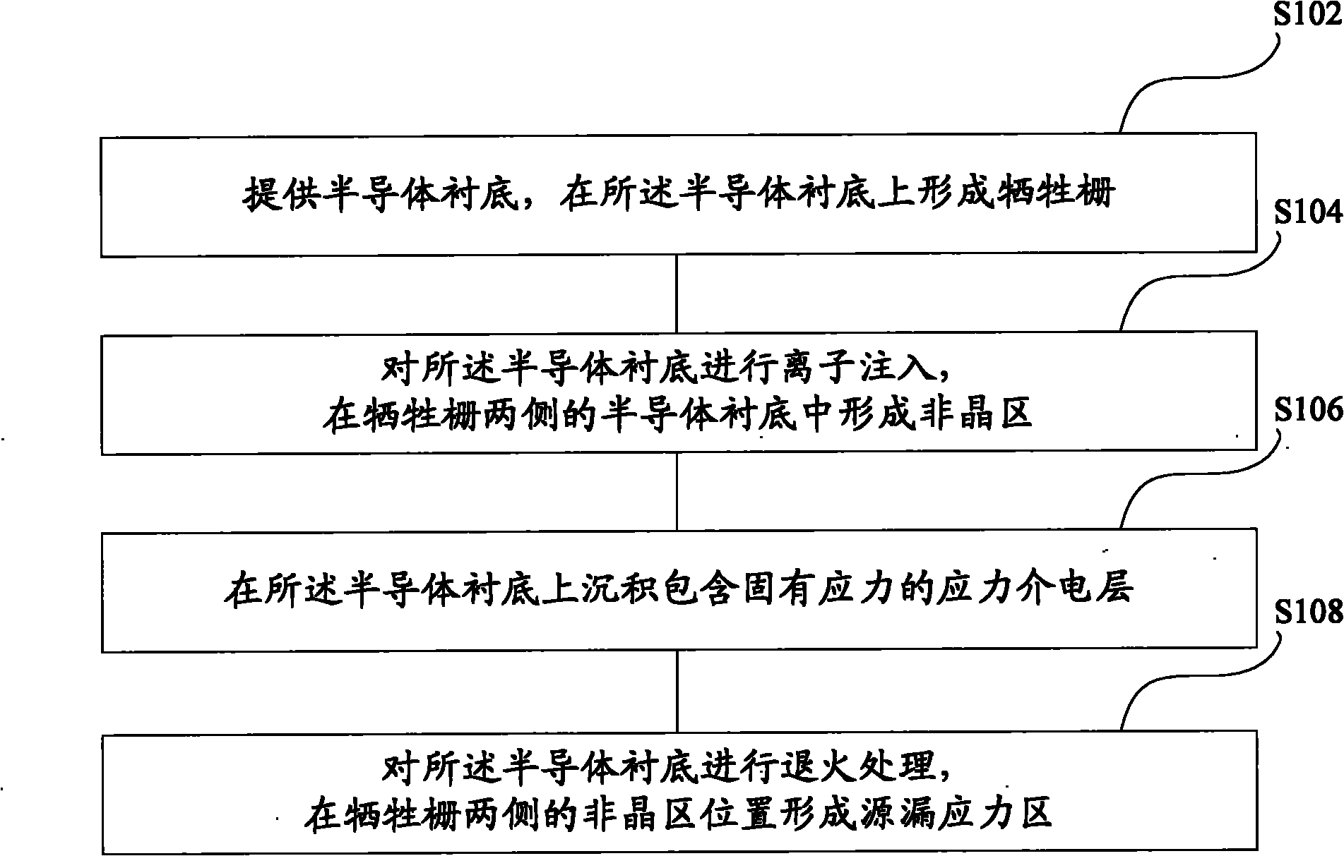
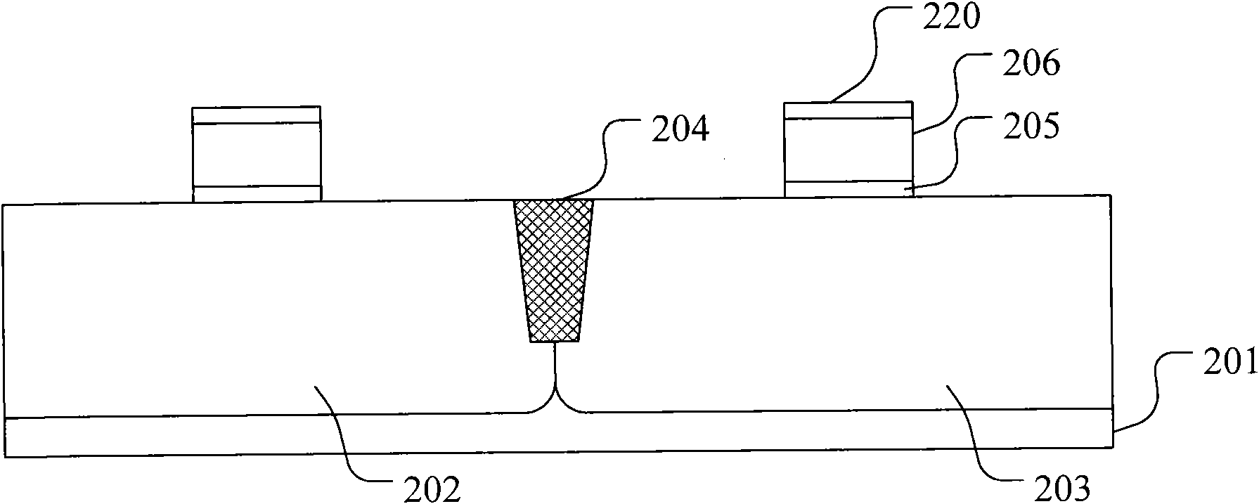
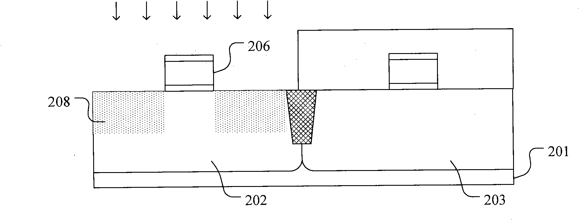
The invention relates to a forming method of a metal-oxide semiconductor (MOS) transistor source drain stress area, which comprises the steps that: a semi-conductor substrate is provided, and a sacrifice grid is formed on the semi-conductor substrate; ions are implanted into the semi-conductor substrate, and an amorphous area is formed in the semi-conductor substrate on both sides of the sacrifice grid; a dielectric layer which contains inherent stress is formed on the semi-conductor substrate; the semi-conductor substrate is annealed; and a source drain stress area is formed in the amorphous area on both sides of the sacrifice grid. The forming method of the MOS transistor source drain stress area reduces the difficulty in filling a stress film above a source drain is reduced and greatly improves the stress conversion proportion to a channel by directly forming the dielectric layer which contains the inherent stress on the source drain area on both sides of a grid to introduce stress. Simultaneously, the semi-conductor substrate which is pre-amorphousized in the source drain area transfers the stress into the source drain area, so that the stress of an original etched dielectric layer and a channel area after a side wall is formed is still maintained, and the stress changes improve the carrier mobility.

Description

technical field [0001] The invention relates to the technical field of semiconductors, and more specifically, the invention relates to a method for forming a source-drain stress region of a MOS transistor and a method for manufacturing the MOS transistor. Background technique [0002] With the continuous development of integrated circuit manufacturing technology, the feature size of MOS transistors is getting smaller and smaller. However, while the feature size of MOS transistors keeps shrinking, the contradiction between device power consumption and speed becomes increasingly prominent, which hinders the further development of integrated circuit technology. [0003] Improving the carrier mobility in the channel region of the MOS transistor is an effective means to solve the power consumption-speed contradiction. On the basis of the substantial increase in the carrier mobility in the channel region, the MOS transistor can use a lower power supply voltage to reduce power con...

Claims


Application Information

Patent Timeline
Patent Type & Authority Applications(China)
IPC IPC(8): H01L21/336H01L21/314H01L21/8238
Inventor 梁擎擎朱慧珑钟汇才
Owner INST OF MICROELECTRONICS CHINESE ACAD OF SCI
Learn More