Vacuum processing equipment and temperature control method thereof, and semiconductor device processing method

A technology for processing equipment and semiconductors, applied in the fields of semiconductor devices, semiconductor/solid-state device manufacturing, electrical components, etc., can solve the problems of particle pollution, less use time, reduced production capacity, etc., to improve pollution conditions, reduce maintenance frequency, and improve equipment. The effect of productivity

Active Publication Date: 2012-03-14
BEIJING NAURA MICROELECTRONICS EQUIP CO LTD
View PDF5 Cites 9 Cited by
  • Summary
  • Abstract
  • Description
  • Claims
  • Application Information

AI Technical Summary

Problems solved by technology

When the by-products accumulate to a certain extent, it will have a serious adverse effect on the results of the etching process, such as particle contamination, process drift, etc.
Therefore, it is necessary to regularly clean and maintain the parts in the chamber, but the higher the maintenance frequency, the less the actual process usage time of the equipment, which not only increases the production cost but also reduces the production capacity

Method used


Image

  • Vacuum processing equipment and temperature control method thereof, and semiconductor device processing method
  • Vacuum processing equipment and temperature control method thereof, and semiconductor device processing method
  • Vacuum processing equipment and temperature control method thereof, and semiconductor device processing method

Examples


Embodiment 1

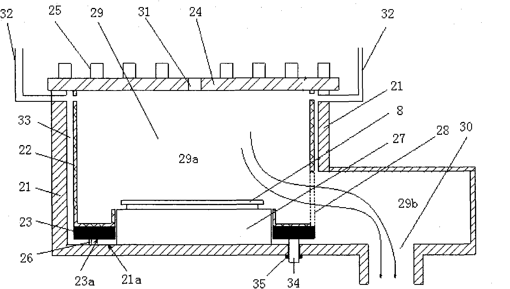
[0044] figure 2 It is a schematic structural diagram of the LED etching machine in this embodiment. As shown in the figure, the LED etching machine includes: a chamber 21 , a lining 22 , a heater 23 , a window 24 and a radio frequency coil 25 .

[0045] The chamber 21 and the window 24 together form a closed space 29, the closed space 29 includes a process chamber 29a and an air extraction chamber 29b. The air extraction chamber 29b is arranged on the side of the bottom of the process chamber 29a; the process chamber of the chamber 21 29a is, for example, cylindrical, and the bottom of its side wall is provided with an exhaust passage 28, which communicates the process chamber 29a and the air extraction chamber 29b, and the bottom of the air extraction chamber 29b is provided with an air extraction port 30, which is connected to the external vacuum device ( not shown) connection.

[0046] The window 24 is located at the top of the chamber 21 to close the chamber 21; the radi...

Embodiment 2

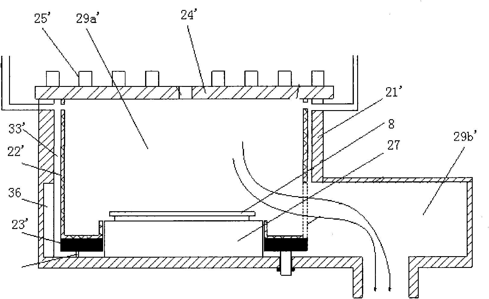
[0059] image 3 It is a schematic diagram of the structure of the LED etching machine in this embodiment. As shown in the figure, the structure of the LED etching machine is similar to that of the first embodiment, and also includes: a chamber 21', a lining 22', a heater 23', a window body 24' and radio frequency coil 25', etc.

[0060] The difference is that the lower part of the side wall of the chamber 21' (that is, the part of the side wall close to the bottom of the chamber) has an annular groove 36, the annular groove surrounds the cylindrical process chamber 29a', the height of which is the same as that of one side of the process chamber. The pumping chamber 29b' is the same. Due to the existence of the annular groove 36, the width of the gap 33' is not uniform from top to bottom. Compared with the upper part of the cavity 21', there is an additional annular groove space between the lining 22' and the cavity 21', Thus, the influence of the high temperature at the bott...

Embodiment 3

[0066] Figure 4 This is a flowchart of the temperature control method of the vacuum processing equipment in this embodiment, wherein the vacuum processing equipment may be any LED etching machine in the above embodiments.

[0067] Step S1: setting the lining temperature as the first temperature, and setting the chamber temperature as the second temperature;

[0068] Step S2: heating the lining to the first temperature by the heater, and heating the chamber to the second temperature by the temperature control device;

[0069] Wherein, the second temperature is higher than the evaporation point of the reaction by-product, and the first temperature is lower than the evaporation point of the reaction by-product.

[0070] For example, in an LED etching process or a process in which by-products such as metal etching are generated, the first temperature is about 150 degrees Celsius, and the second temperature is about 50 degrees Celsius, which can effectively avoid side effects of ...


PUM


Abstract

The invention provides vacuum processing equipment and a temperature control method thereof. The vacuum processing equipment comprises a cavity, a lining positioned inside the cavity, and a heater which is arranged inside the cavity and connected with the lining in a contact manner, wherein a gap is reserved between the lining and the cavity; preferably, the heater is positioned under the lining; and the upper surface of the heater is well contacted with the lower surface of the lining. In the vacuum processing equipment, the heater is arranged inside the cavity and connected with the lining in the contact manner, and the gap is reserved between the lining and the cavity, so the cavity and the lining can be subjected to temperature setting and control respectively by independently controlling temperature of the lining through the heater; for example, the temperature of the lining is set to be higher than an evaporating point of most byproducts generated by etching reaction, so attachment of the byproducts to the wall of the lining can be reduced and the fallen byproducts are pumped away by a vacuum pump; therefore, the pollution situation in the cavity can be improved, the maintenance frequency can be reduced and the yield of the equipment can be increased.

Description

technical field [0001] The invention relates to the technical field of semiconductor processing, in particular to a vacuum processing equipment, a temperature control method thereof, and a semiconductor device processing method. Background technique [0002] LED etching machine is a very important equipment in the production process of LED light source. Usually, GaN-based epitaxial layer or sapphire substrate is the main object of etching. The effect of the etching process is directly related to the quality of the LED chip, which in turn affects the quality of the light source. [0003] The LED etching machine includes a transmission module and a process module, both of which jointly affect the efficiency of etching (ie, equipment capacity), and the effect of etching is mainly determined by the process module. Among them, the chamber design of the process module affects the etching process. The effect has the greatest impact. For example, during the etching process, many b...

Claims


Application Information

Patent Timeline
Patent Type & Authority Applications(China)
IPC IPC(8): H01L21/67H01L33/00
Inventor 管长乐
Owner BEIJING NAURA MICROELECTRONICS EQUIP CO LTD
Why Eureka
Try Eureka