Light emitting apparatus and method for manufacturing thereof
一种发光装置、制造方法的技术,应用在发光材料、化学仪器和方法、用于材料和表面科学的纳米技术等方向,能够解决难以得到颜色再现性和明亮度、发光装置劣化加剧、发光效率降低等问题,达到提高颜色再现性、缓和光散射、提高明亮度的效果
- Summary
- Abstract
- Description
- Claims
- Application Information
AI Technical Summary
Problems solved by technology
Method used
Image

Examples
Embodiment approach 1
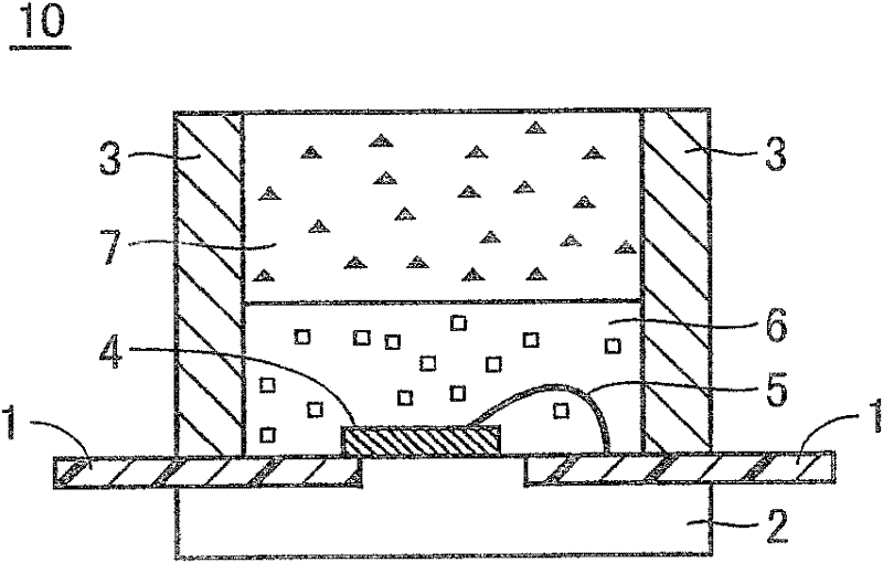
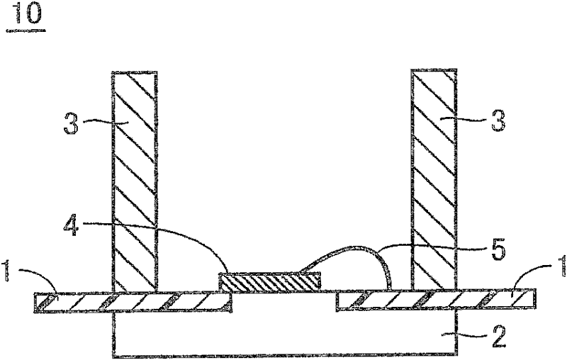
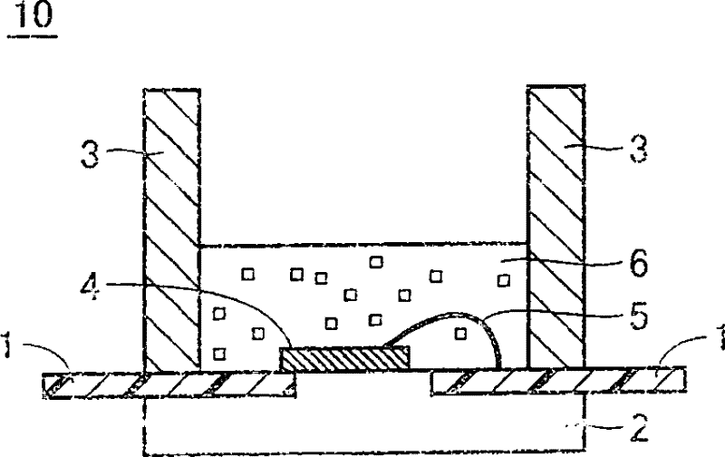
[0037] figure 1 It is a sectional view of the light emitting device of this embodiment. The light-emitting device 10 is composed of a substrate 2 on which an electrode 1 is formed, a package 3 and a light-emitting element 4 provided on the electrode 1 , a wire 5 connecting the light-emitting element 4 and the electrode 1 , and a wavelength conversion unit. In this wavelength conversion part, a first wavelength conversion part 6 containing semiconductor nanoparticles and a second wavelength conversion part 7 containing Eu-activated β-type sialon phosphors are laminated in the order of the optical path of the light emitting element 4 .
[0038] The electrode 1 is electrically connected to the light emitting element 4 through a metal wire 5 . As the conductor constituting the electrode 1, it is necessary to use a material having a function of electrically connecting the electrical conduction path of the light-emitting element 4, specifically, a metallized layer containing metal...
Embodiment approach 2
[0057] Next, three types of light-emitting devices in which the content of the Eu-activated β-type sialon phosphor contained in the second wavelength converting portion was changed were produced by the same method as in the first embodiment. That is, the amount of the Eu-activated β-type sialon phosphor contained in the silicone resin (SCR1011) per 1 g of the second wavelength conversion part 7 was prepared to be (I) 0.03 g, (II) 0.1 g, (III) ) 0.3g of three light-emitting devices. In addition, as the silicone resin 8, SCR1011 is used in the same manner as in the embodiment, and it is laminated with figure 1 The shown second wavelength conversion parts have substantially the same thickness.
Embodiment approach 3
[0067] This embodiment is the same as the light-emitting device of Embodiment 1 except that the resin sheet 8 is included in the second wavelength converting portion 7 of Embodiment 1. FIG. Figure 8 It is a cross-sectional view of the light emitting device of the third embodiment. The resin sheet 8 dispersed and kneaded in the second wavelength conversion part 7 is not particularly limited as long as it is an optically transparent material, and silicone or epoxy-based materials are mainly used. The shape of the resin sheet 8 is generally a bead shape, but is not limited thereto. However, the size of the resin sheet 8 is preferably uniform. In this embodiment, the resin sheet whose refractive index is the same as or close to the resin layer which comprises the 2nd wavelength conversion part 7 is used. In addition, light scattering may be utilized by making the refractive index of the resin sheet different from that of the resin layer. In addition, although a resin sheet is ...
PUM
 Abstract
Description
Claims
Application Information
 - R&D
- Intellectual Property
- Life Sciences
- Materials
- Tech Scout
- Unparalleled Data Quality
- Higher Quality Content
- 60% Fewer Hallucinations
Browse by: Latest US Patents, China's latest patents, Technical Efficacy Thesaurus, Application Domain, Technology Topic, Popular Technical Reports.
© 2025 PatSnap. All rights reserved.Legal|Privacy policy|Modern Slavery Act Transparency Statement|Sitemap|About US| Contact US: help@patsnap.com