
Preparation method of direct methanol fuel cell anode catalyst

A methanol fuel cell and catalyst technology, applied in battery electrodes, chemical instruments and methods, physical/chemical process catalysts, etc., can solve the problems of scarce resources, high price, high cost, etc., and achieve self-agglomeration, improve utilization, and improve catalytic performance. Effect

Inactive Publication Date: 2012-03-21
NANCHANG UNIV
View PDF3 Cites 15 Cited by
  • Summary
  • Abstract
  • Description
  • Claims
  • Application Information

AI Technical Summary

Problems solved by technology

Platinum-based alloy catalysts can significantly improve the catalytic effect and anti-poisoning ability of methanol, but the second metals used in the literature are noble metals such as Pd, Au and Ag, and noble metals such as Pd, Au and Ag are also facing the scarcity of resources and the Expensive and other issues

Method used


Image

  • Preparation method of direct methanol fuel cell anode catalyst
  • Preparation method of direct methanol fuel cell anode catalyst
  • Preparation method of direct methanol fuel cell anode catalyst

Examples


Embodiment 1

[0028] (1) Preparation of graphene: 1.0 g graphite and 1.0 g NaNO 3 Add to 46 mL of 98% H 2 SO 4 The solution was mechanically stirred in an ice bath for 20 minutes, then slowly added 6.0 g KMnO 4 and 80 mL of secondary water, the temperature was controlled at 90 ± 5 °C; after stirring for 30 minutes, 200 mL of secondary water was added to the reaction system and 6 mL of 30% H 2 o 2 The solution was filtered while it was hot, and washed with secondary water until the filtrate was neutral; the obtained product was dispersed in 500 mL of secondary water, and ultrasonicated for 2 hours to obtain uniformly dispersed single-sheet graphene.

[0029] (2) Preparation of PEI-functionalized graphene: ultrasonically disperse 20 mg of graphene in 50 mL of 1 mol / L NaCl solution, then add 1.08 g of PEI, continue ultrasonication for 4.5 hours; then centrifuge the reaction solution and wash it with secondary water , the product was vacuum-dried at 40 °C for 48 hours, and the product was ...

Embodiment 2

[0032] (1) Preparation of graphene: 1.0 g graphite and 1.0 g NaNO 3 Add to 46 mL of 98% H 2 SO 4 The solution was mechanically stirred in an ice bath for 20 minutes, then slowly added 6.0 g KMnO 4 and 80 mL of secondary water, the temperature was controlled at 90 ± 5 °C; after stirring for 30 minutes, 200 mL of secondary water was added to the reaction system and 6 mL of 30% H 2 o 2 The solution was filtered while it was hot, and washed with secondary water until the filtrate was neutral; the obtained product was dispersed in 500 mL of secondary water, and ultrasonicated for 2 hours to obtain uniformly dispersed single-sheet graphene.

[0033] (2) Preparation of PEI-functionalized graphene: Disperse 20 mg graphene in 50 mL 1 mol / L NaCl solution, add 1.08 g PEI after ultrasonication for 1 hour, and continue ultrasonication for 4.5 hours; After washing with water, the product was vacuum-dried at 40 °C for 48 hours, and the product was labeled as PEI-graphene.

[0034] (3) P...


PUM


Abstract

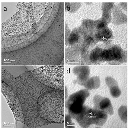
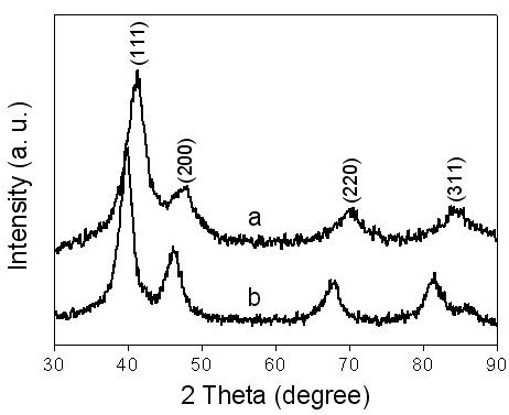
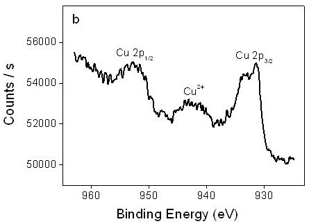
The invention discloses a preparation method of a direct methanol fuel cell anode catalyst, and belongs to the technical field of electrocatalysis and energy. The method comprises the following steps: firstly preparing polyethyleneimine (PEI) functionalized graphene, then mixing H2PtCl6, CuCl2 and PEI functionalized graphene according to a certain mass ratio, dispersing in secondary water by ultrasonic, performing in-situ reduction of H2PtCl6 and CuCl2 by sodium borohydride under a room temperature condition so as to prepare a PtCu two-component nanoparticle / graphene catalyst (PtCu / graphene). The PtCu two-component nanoparticles (PtCuNPs) prepared by the method of the invention are uniformly dispersed on PEI functionalized graphene, and the particle size of the PtCu alloy nanoparticles is about 4-6 nm. Electrochemical experiment results show that the PtCu / graphene catalyst has excellent electrocatalytic activity for methanol oxidation; and the method is simple in operation, is mild and controllable in experiment conditions, and has extensive application prospects.

Description

technical field [0001] The invention relates to a preparation method of an anode catalyst, in particular to a preparation method of a direct methanol fuel cell anode catalyst. Background technique [0002] A fuel cell is an energy device that directly converts the chemical energy of fuel into electrical energy by chemical reaction without combustion. It has the advantages of high energy conversion density, low pollution, diverse fuels, high reliability, low noise and easy maintenance. , has been highly valued by countries all over the world. In particular, the research on direct methanol fuel cells has attracted more attention, because it can be widely used in power sources, mobile phones and laptop computers, etc., and is considered one of the most likely alternative energy technologies for large-scale commercial applications. However, the anode catalyst of the direct methanol fuel cell has low electrocatalytic activity, and the CO produced during the electrocatalytic oxi...

Claims


Application Information

Patent Timeline
IPC IPC(8): B01J23/42B01J23/89H01M4/92
CPCY02E60/50
Inventor 邱建丁王果冲梁汝萍刘晓晨
Owner NANCHANG UNIV
Learn More