Miniature semi-active folding flapping wing

A semi-active and miniature technology, applied in the field of folding flapping wings, can solve the problems of increasing the complexity and weight of the flapping wing drive mechanism, reducing the reliability of the flapping wing driving mechanism, increasing the weight and moment of inertia of the wing, and achieving low weight cost. , Efficiency improvement, the effect of improving aerodynamic efficiency

Inactive Publication Date: 2012-03-21
NORTHWESTERN POLYTECHNICAL UNIV
View PDF6 Cites 17 Cited by
  • Summary
  • Abstract
  • Description
  • Claims
  • Application Information

AI Technical Summary

Problems solved by technology

The disadvantage of this method is that it increases the complexity and weight of the flapping wing drive mechanism and reduces the reliability of the flapping wing drive mechanism
The disadvantage is that the blade and its mechanism will increase the weight and moment of inertia of the wing, increase the power required for flapping, and reduce the life of the flapping mechanism and the wing itself; the opening and closing of the blade needs to cooperate with the flapping position to increase control difficulty
Its shortcoming is that the folding effect is completely passively produced by the elastic material under the action of aerodynamic force. When the flapping frequency of the flapping wing is high, the folding effect will be weakened to a considerable extent; the aging and life of the elastic material directly affect the flapping wing. Overall performance and longevity

Method used


Image

  • Miniature semi-active folding flapping wing
  • Miniature semi-active folding flapping wing
  • Miniature semi-active folding flapping wing

Examples


Embodiment Construction

[0025] The present invention will be further described in detail below in conjunction with the accompanying drawings and specific embodiments.

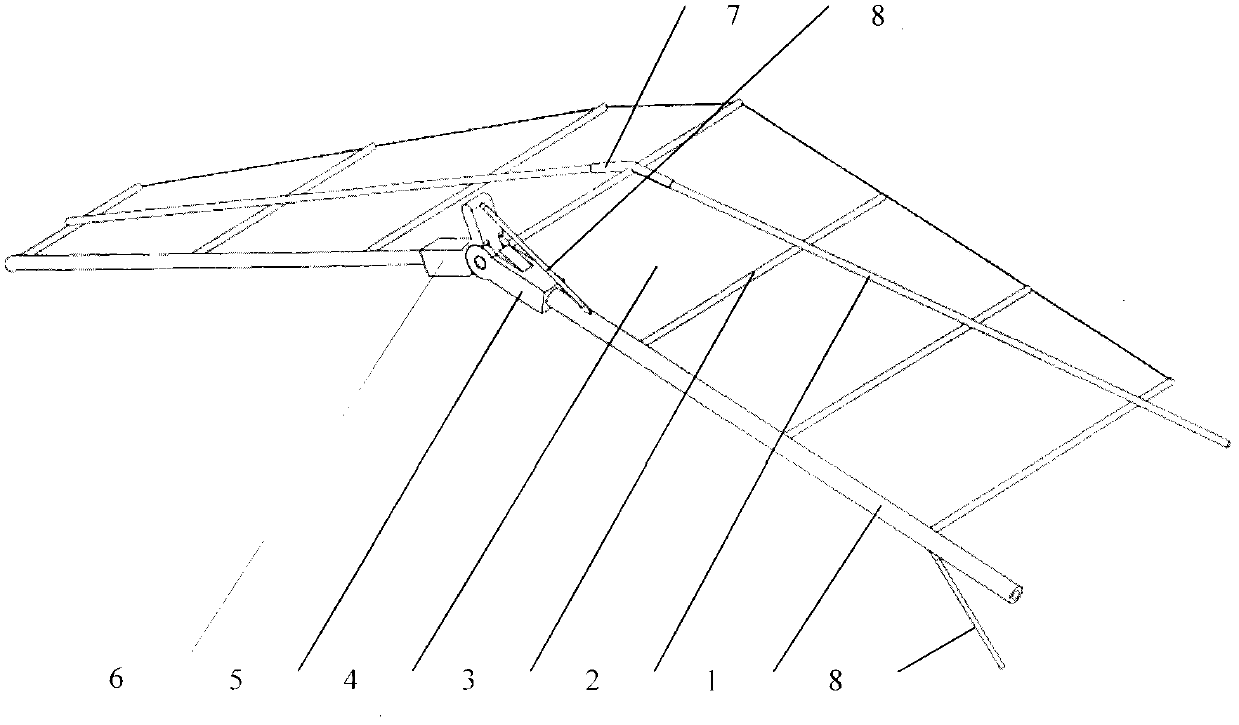
[0026] The miniature semi-active folding flapping wing of the present invention is composed of a front beam 1, a slanting beam 2, a wing rib 3, and a skin 4. The material of the front beam, the slanting beam and the wing rib is a resin-based carbon fiber composite material, and the skin is a puncture-resistant polyether film.

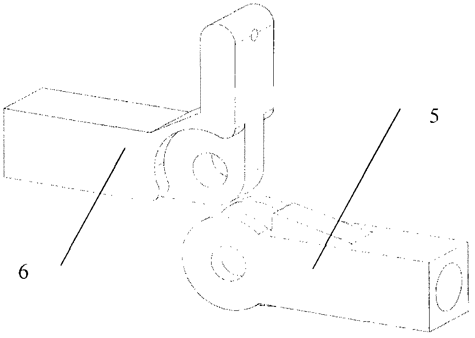
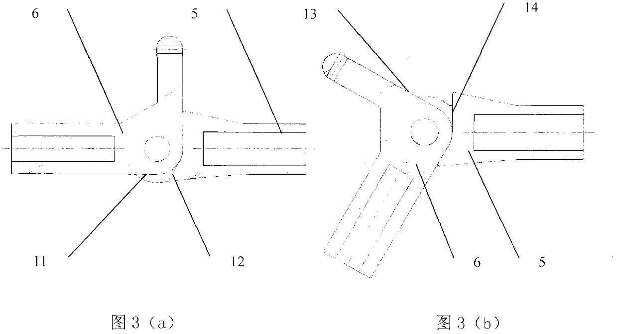
[0027] The front spar is parallel to the span direction and is located at the leading edge of the flapping wing; the oblique spar is located chordwise behind the front spar at an acute angle to the span direction, and its endpoint at the wing tip is closer to the flapping wing than its endpoint at the wing root leading edge. The front beam and the inclined beam are divided into two sections in the middle of the wingspan direction. The inner section 1A of the front beam is hollow and is fixedly connected to the...


PUM


Abstract

The invention discloses a miniature semi-active folding flapping wing, which consists of a front beam, an inclined beam, wing ribs and covers. The front beam and the inclined beam are respectively divided into two sections from an middle part; the inner section and the outer section of the front beam are respectively fixed to a folding base and a folding head; a rocker arm of the folding head is connected with a soft steel wire rope; the soft steel wire rope penetrates through the inner section of the front beam and is fixedly connected with a frame of a flapping wing driving mechanism; and a root part of the inner section of the front beam is connected with an output rocker arm of the flapping wing driving mechanism in an inserting manner. In a process that the flapping wing downwardly flaps, the flapping wing keeps flat and straight, and in an upwardly flapping process, the outer section of the flapping wing is downwardly bent to a certain angle due to the action of aerodynamic forces, and further, gradually becomes flat and straight along with the straining of the steel wire rope. According to the miniature semi-active folding flapping wing, the asymmetric upward / downward flapping of the flapping wing is realized through a simple and reliable manner, a resultant force of the aerodynamic lifting forces in a flapping cycle is increased, the aerodynamic efficiency of the flapping wing is increased, and thus, the miniature semi-active folding flapping wing is applicable to a miniature flapping wing flying vehicle.

Description

technical field [0001] The invention relates to a folding flapping wing. Background technique [0002] The micro flapping wing aircraft is a new concept aircraft that imitates the flight of birds. It has the advantages of small size, light weight, good concealment, flexible use, and high efficiency. If it is equipped with sensors and related data transmission and flight control systems, it will form a micro A small flapping wing UAV platform will have broad application prospects. Around this subject, various countries have developed controllable flapping-wing aircraft, among which the more successful ones are the “Microbat” jointly developed by Aero Vironment of the United States and the University of California, and the “Delfly” developed by Delft University in the Netherlands. There is still a big gap, which is mainly reflected in the limited flight time, small payload, and difficult control. Tracing it to its cause, the low aerodynamic efficiency of the wing of flapping...

Claims


Application Information

Patent Timeline
Patent Type & Authority Applications(China)
IPC IPC(8): B64C33/00B64C33/02
Inventor 李洋宋笔锋樊邦奎鲁合营杨文青王利光高广林
Owner NORTHWESTERN POLYTECHNICAL UNIV
Why Eureka
Try Eureka