Water surface oil recovering device

A technology for collecting oil tanks and oil tankers, which is applied to the cleaning of open water surfaces, water conservancy projects, and general water supply conservation. It can solve the problems of low recovery efficiency of thin oil layers, recovery of emulsified oil and high-viscosity oil that are not easy to be scraped off, and achieve enhanced Deoiling effect, promoting flow, highlighting the effect of energy saving and environmental protection

Inactive Publication Date: 2012-03-21
HARBIN INST OF TECH
View PDF5 Cites 10 Cited by
  • Summary
  • Abstract
  • Description
  • Claims
  • Application Information

AI Technical Summary

Problems solved by technology

[0005] The purpose of the present invention is to provide a water surface oil collection device to solve the problems of low recovery efficiency of thin oil layer and recovery of emulsified oil and high-viscosity oil that are not easy to be scraped off

Method used


Image

  • Water surface oil recovering device
  • Water surface oil recovering device
  • Water surface oil recovering device

Examples


specific Embodiment approach 1

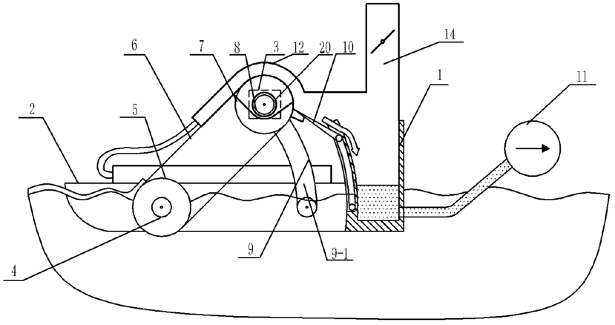
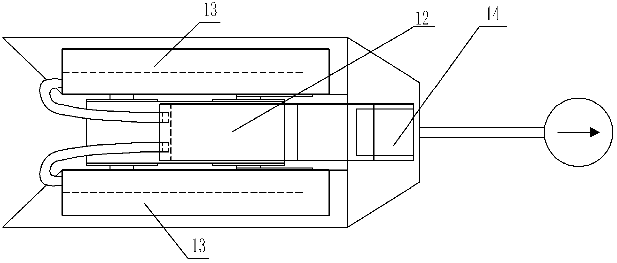
[0017] Specific implementation mode one: combine figure 1 and figure 2 Describe this embodiment, the device of this embodiment comprises oil receiving tank 1 and support frame 2, described device also comprises motor 3, oil suction wheel shaft 4, oil suction wheel 5, oil removal belt 6, deoiling wheel 7, deoiling wheel shaft 8, scraper Sheet 10, light-transmitting flow guide heat preservation cover 12, solar chimney 14, two angle adjustment brackets 9, two solar air heat collectors 13 and two shaft support seats 20, the oil collection tank 1 is fixed on the side wall of the support frame 2 On, two solar air heat collectors 13 are housed on the support frame 2, the deoiling wheel shaft 8 is contained on the two shaft support seats 20, the motor 3 is fixed on the shaft support seats 20, and the output shaft of the motor 3 can be connected with the deoiler The wheel shaft 8 is connected by transmission, and can also be pressed and contacted with the oil removal belt 6 through a...

specific Embodiment approach 2

[0019] Specific implementation mode two: combination figure 1 and figure 2 To illustrate this embodiment, the degreasing belt 6 of this embodiment is a flat belt, a toothed belt or a chain brush belt, and the degreasing belt is black or the surface is painted with a paint with strong radiation absorption capacity. Choose different types of oil removal belts according to the thickness of the oil layer and the characteristics of the oil. Other components and connections are the same as those in the first embodiment.

specific Embodiment approach 3

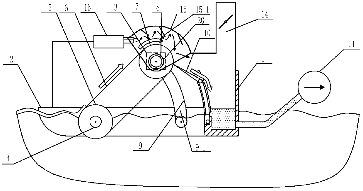
[0020] Specific implementation mode three: combination image 3Describe this embodiment, the device of this embodiment comprises oil receiving tank 1 and support frame 2, described device also comprises motor 3, oil suction wheel shaft 4, oil suction wheel 5, oil removal belt 6, deoiling wheel 7, deoiling wheel shaft 8, scraper Sheet 10, exhaust chimney 14, light-transmitting flow guide heat preservation cover 15, guide vane 15-1, hot air blower 16, two angle adjustment brackets 9 and two shaft support seats 20, the oil collection tank 1 is fixed on the support frame 2 On the side wall of the motor 3, the output shaft of the motor 3 can be transmission-connected with the deoiling wheel shaft 8, and can also be pressed and contacted with the deoiling belt 6 through an independent wheel shaft to drive its movement. The deoiling wheel shaft 8 is installed on two shaft support seats 20 Above, the motor 3 is fixed on the shaft support seat 20, the oil removal wheel 7 is mounted on ...


PUM


Abstract

The invention relates to an oil recovering device, in particular to a water surface oil recovering device. The oil recovering device solves the problems that the traditional mechanical device has low recovery rate for a thin oil layer when recovering water surface floating oil, and emulsified oil and high-viscosity oil are difficult to scrape off during recovery. An oil recovering box is fixedly arranged on the side wall of a support bracket; an output shaft of a motor is in drive connection with a deoiling wheel shaft; an oil sucking wheel is installed on an oil sucking wheel shaft; the oil sucking wheel and a deoiling wheel are in drive connection by a deoiling belt; and a wind outlet of a solar air heat collector is communicated with a wind inlet of a transmitting flow guide heat insulating shield. The transmitting flow guide heat insulating shield is positioned above the deoiling wheel and communicated with a solar chimney. The second scheme is characterized in that the water surface oil recovering device is heated by an air heater; a flow guide blade is arranged in the transmitting flow guide heat insulating shield; and an angle between the flow guide blade and the wind outlet of the air heater is an acute angle. The third scheme is characterized in that the water surface oil recovering device is heated by the air heater, and a transmitting wind guide pipe is communicatedwith a plurality of branch pipes. The fourth scheme is characterized in that an electric heating component is installed in the deoiling wheel for heating. The water surface oil recovering device is used for water surface oil recovery.

Description

technical field [0001] The invention relates to an oil collecting device. Background technique [0002] With the rapid development of human society, the demand for fossil energy is increasing. Among them, oil has become a resource that the world economy relies heavily on. Oil transportation is mainly carried out by shipping and pipeline transportation. Once an oil spill occurs, the oil spill will have a serious impact and damage on the surrounding ecology. It often takes decades for the ecological environment of the affected area to recover. [0003] The impact of marine oil spill accidents on the ecological environment is particularly serious, and its treatment techniques are generally divided into physical methods, chemical methods and biological methods. The chemical method is more efficient, but its disadvantages are combustion residues and secondary pollution; although the biological method is environmentally friendly, its degradation rate is too slow to meet the need...

Claims


Application Information

Patent Timeline
Patent Type & Authority Applications(China)
IPC IPC(8): E02B15/10
CPCY02A20/204
Inventor 高继慧黄彬薛骅朱玉雯陈国庆李阳吴少华
Owner HARBIN INST OF TECH
Why Eureka
Try Eureka