Automatic gas diluter
A diluter and automatic technology, applied in gas discharge, safety devices, mining equipment and other directions, can solve the problems of complex structure and high cost, and achieve the effects of simple structure, low production cost, and easy processing and implementation.
- Summary
- Abstract
- Description
- Claims
- Application Information
AI Technical Summary
Problems solved by technology
Method used
Image
Examples
Embodiment 1
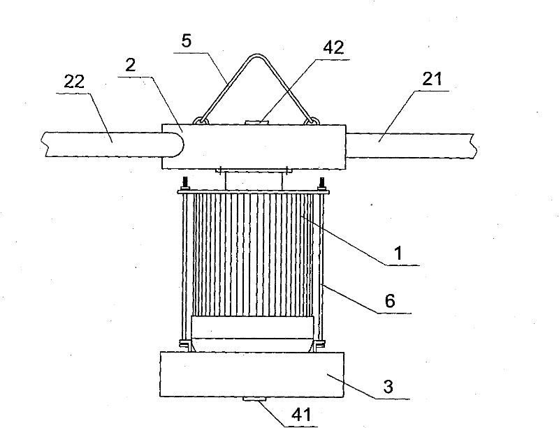
[0020] Example 1: see figure 1 , an automatic gas diluter, the fan includes a motor 1 and a wind turbine chamber 2 . The output shaft of the motor 1 is connected with the turbine in the wind turbine chamber 2 upwardly. A hanger 5 is arranged above the wind turbine chamber 2. After drilling a hole on the top of the upper corner and fixing the hook, the hanger 5 is hung on the hook. A battery casing 3 is fixed to the lower part of the motor 1 through a support rod 6, and a battery and a control circuit board are sealed and installed in the battery casing 3. Gas concentration sensors 41 and 42 are installed on the battery casing 3 and the wind turbine chamber casing 2 respectively. The gas concentration sensor is sealed with the input end of the control circuit board, and the battery is sealed with the control circuit board, and the output of the control circuit board is sealed. The end is sealed with the motor input end. Motor 1 adopts explosion-proof motor.
Embodiment 2
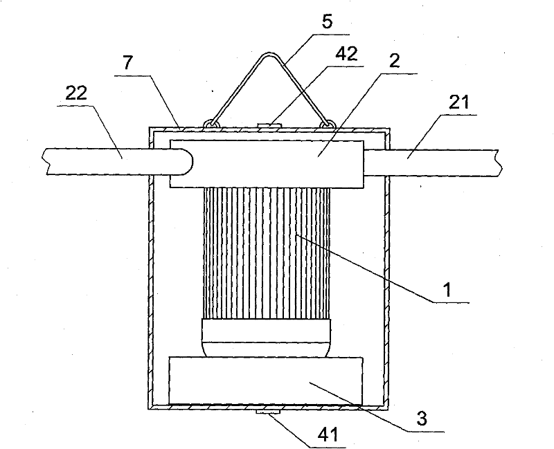
[0021] Example 2: see figure 2 , another gas automatic diluter, the content is basically the same as that of the first embodiment, the same is not repeated, the difference is: it also includes a closed support shell 7, the battery, the motor and the wind turbine room are installed on the support In the casing, the probes of the gas concentration sensor may be multiple, and they are respectively located on the side wall of the airtight casing. A hanger 5 is fixed on the upper part of the airtight casing, and the air inlet pipe 21 and the air outlet pipe 22 of the wind turbine chamber are respectively fixed on the left and right side walls of the supporting casing. Due to the function of the airtight support shell, the motor can be an explosion-proof motor or an ordinary motor.
Embodiment 3
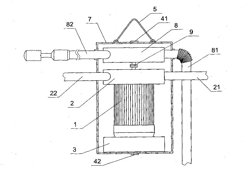
[0022] Example 3: see image 3 , Another gas automatic diluter, the content is basically the same as that of the second embodiment, and the similarities will not be repeated. A water turbine chamber 8 is also provided in the closed support shell 7, and the motor output shaft is simultaneously connected with the wind turbine chamber 2 and the water turbine chamber 8. The turbines in the turbine chamber 8 are connected by transmission. The water inlet pipe 81 and the water outlet pipe 82 of the water turbine chamber 8 are respectively fixed on the side walls of the support shell, and the water inlet pipe can communicate with the water container on the ground. In this embodiment, an electric clutch 9 is installed on the transmission shaft between the wind turbine chamber 2 and the water turbine chamber 8 , and the signal wire of the electric clutch 9 is sealedly connected with the output end of the control circuit board. The water outlet pipe 82 is a jet outlet water pipe.
PUM
 Abstract
Description
Claims
Application Information
 - R&D
- Intellectual Property
- Life Sciences
- Materials
- Tech Scout
- Unparalleled Data Quality
- Higher Quality Content
- 60% Fewer Hallucinations
Browse by: Latest US Patents, China's latest patents, Technical Efficacy Thesaurus, Application Domain, Technology Topic, Popular Technical Reports.
© 2025 PatSnap. All rights reserved.Legal|Privacy policy|Modern Slavery Act Transparency Statement|Sitemap|About US| Contact US: help@patsnap.com


