Collecting pipe and heat exchanger with same

A technology of headers and flow tubes, applied in the direction of heat exchanger shells, indirect heat exchangers, heat exchanger types, etc., can solve the problems of increased flow resistance of refrigerant, reduced flow rate of refrigerant, and increased material cost, etc., to achieve good results The effect of diversion, uniform distribution and low cost

Inactive Publication Date: 2012-03-21
GREE ELECTRIC APPLIANCES INC
View PDF10 Cites 43 Cited by
  • Summary
  • Abstract
  • Description
  • Claims
  • Application Information

AI Technical Summary

Problems solved by technology

First of all, in order to achieve uniform flow distribution, it is necessary to open through holes of unequal distance or area on the shunt pipe. It is technically difficult to open such non-equidistant and equal-area through holes and large holes in the shunt pipe; in addition, If the diameter of the header pipe of the original heat exchanger remains unchanged, the diameter of the shunt pipe is limited. In order to ensure the strength of the shunt pipe, the area of ​​a single shunt h

Method used


Image

  • Collecting pipe and heat exchanger with same
  • Collecting pipe and heat exchanger with same
  • Collecting pipe and heat exchanger with same

Examples


Embodiment 1

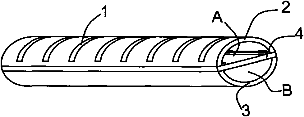
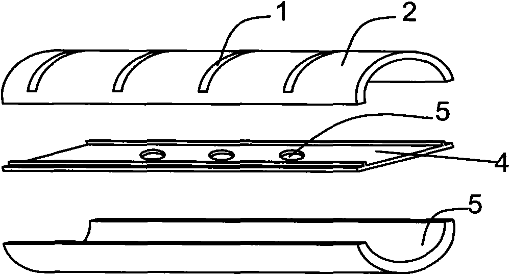
[0037] Such as Figure 2 to Figure 7 As shown, among them, Figure 7 A schematic diagram of the combination of the header and heat exchange tubes of the present invention is shown. The collecting pipe includes: an upper collecting pipe wall 2 , a lower collecting pipe wall 3 , and a distribution orifice plate 4 . Wherein, the upper header wall 2 is horizontally provided with a plurality of connection holes 1, and the connection holes 1 are used to connect heat exchange flat tubes 6 (such as Figure 4 or Figure 7 shown), the distribution orifice 4 is located between the upper collector wall 2 and the lower collector wall 3; the lower collector wall 3 surrounds the upper collector wall 2, the distribution orifice 4 outside, through the positioning of the bosses 31 on both sides of the lower header wall 3, the upper header 2, the lower header 3, and the distribution orifice 4 are fixed by welding, the upper header wall 2, the The lower collector wall 3 surrounds the distribu...

Embodiment 2

[0043] Such as Figure 9 shown. The difference between Embodiment 2 and Embodiment 1 is that the cross-sectional shapes of the upper collector wall 2 and the lower collector wall 3 are rectangular, and the ends of the upper collector wall 2 are bent inward to form The positioning device 8 is used to limit the insertion depth of the heat exchange flat tube into the header. The rectangular header of this embodiment is conducive to reducing the cross-sectional area of ​​the header channel and increasing the flow rate of the refrigerant in the header. In addition, as the width of the heat exchange flat tube increases, the volume of the header increases faster. Small, which can save material cost, save space, and facilitate installation.

Embodiment 3

[0045] Such as Figure 10 and Figure 11 shown. The difference between Embodiment 3 and Embodiment 1 is that the cross-sections of the upper collector wall 2 and the lower collector wall 3 are inconsistent, the cross-section of the upper collector wall 2 is rectangular, and the cross-section of the lower collector wall 3 is rectangular. The area of ​​the cross-section is arc-shaped, of course, the cross-section of the upper collector wall can also be arc-shaped, and the cross-section of the lower collector wall is rectangular; as Figure 11 As shown, the upper part of the distribution orifice 4 is provided with the same positioning device 8 as in Embodiment 1, and the two side ends of the lower bottom surface have recesses 41, and the two ends of the lower header 3 can just be stuck in the recesses 41, and then Fixed by welding.


PUM


Abstract

A heat exchanger comprises a heat exchange flat pipe and a collecting pipe. The heat exchanger can achieve the effect of uniformly distributing refrigerant while being used as an evaporator or a condenser so as to improve the heat exchange performance of the evaporator or the condenser. The collecting pipe comprises an upper collecting pipe wall, a lower collecting pipe and a splitter pore plate for uniformly shunting. A splitter pore is arranged on the splitter pore plate. The splitter pore plate is inserted between the upper collecting pipe wall and the lower collecting pipe and encircles to form an upper cavity and a lower cavity together with the upper collecting pipe wall and the lower collecting pipe. The refrigerant gas firstly enters into the lower cavity, enters into the upper cavity via the splitter pore and finally enters into a heat exchange flat pipe. The refrigerant gas flow entering into the heat exchange flat pipe is uniformly distributed due to shunting action of the splitter pore plate so that the uniform and full heat exchange effect is achieved and the overall heat exchange performance of the heat exchanger is improved.

Description

technical field [0001] The invention relates to the field of air-conditioning heat exchangers, in particular to a header and a heat exchanger with the header. Background technique [0002] When the microchannel heat exchanger is used as an evaporator, the imported refrigerant is generally a gas-liquid two-phase. Such as figure 1 As shown, the headers for existing microchannel heat exchangers are usually directly connected to the heat exchange flat tubes without any diversion measures. After entering the headers, the gas-liquid two-phase stratification phenomenon is obvious, resulting in the refrigerant entering each heat exchange flat tube The distribution is uneven, and the heat transfer performance of the heat exchanger is poor. Moreover, since the heat pump has two operating modes of cooling and heating, the heat exchanger of the outdoor unit involves the mutual conversion of the condenser and the evaporator. For a single-flow heat exchanger, when used as a condenser, ...

Claims


Application Information

Patent Timeline
IPC IPC(8): F28F9/02F28F9/22F28D7/16F25B39/00
Inventor 邢淑敏梁祥飞尹茜
Owner GREE ELECTRIC APPLIANCES INC
Why Eureka
Try Eureka