Stack type battery

A layered, layered electrode technology, used in secondary battery manufacturing, battery pack components, battery boxes/jackets, etc., can solve the problem of unconsidered positioning, time required, position misalignment, etc., to achieve easy and reliable. The effect of positioning, easy production and high precision production

Inactive Publication Date: 2012-03-21
SANYO ELECTRIC CO LTD
View PDF3 Cites 13 Cited by
  • Summary
  • Abstract
  • Description
  • Claims
  • Application Information

AI Technical Summary

Problems solved by technology

[0013] As mentioned above, when the current collecting tab is formed into a bent structure, there is a case where the current collecting tab is particularly unstable at the bent portion and is easy to shake, and the force to restore the bent current collecting tab acts, thereby collecting The electric part is easy to move and it is difficult to fix it in a predetermined position, so there are problems that the position of the current collecting terminal is misplaced, or the sealing performance is deteriorated, or the terminal part is easily damaged.
In the past, the current collector was fixed with a belt, but it was difficult to position it correctly and the operation was cumbersome
[0014] In addition, the laminated electrode body of a laminated battery is produced by alternately laminating positive plates, separators, and negative plates, and finally fixing the whole body with a tape. time, and even if the lamination operation is carried out while being correctly positioned by the equipment, the fixing operation by the belt is prone to misalignment, and it is not easy to ensure accuracy
[0015] Neither Patent Document 1 or 2 discloses that the current collecting tab is formed into a bent structure, and therefore no countermeasures for solving the above-mentioned problem of positioning of the current collecting part accompanying the bent structure are not considered at all.

Method used


Image

  • Stack type battery
  • Stack type battery
  • Stack type battery

Examples


Embodiment Construction

[0060] Hereinafter, the present invention will be described in more detail with reference to the drawings. However, the present invention is not limited to the following best mode at all, and can be appropriately changed and implemented within a range that does not change the gist of the present invention.

[0061] [making of positive electrode]

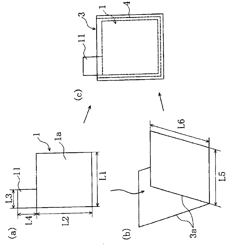
[0062] 90% by mass of LiCoO as the positive electrode active material 2 , 5% by mass of carbon black as a conductive agent, 5% by mass of polyvinylidene fluoride as a binder, and N-methyl-2-pyrrolidone (NMP) solution as a solvent were mixed to prepare a positive electrode slurry. Thereafter, this positive electrode slurry was coated on both surfaces of an aluminum foil (thickness: 15 μm) as a positive electrode current collector. After that, the solvent is removed by heating, and compressed with a roller until the thickness becomes 0.1mm, and then as figure 1 As shown in (a), the positive electrode plate 1 having the positive elect...


PUM

PropertyMeasurementUnit
thicknessaaaaaaaaaa
thicknessaaaaaaaaaa
widthaaaaaaaaaa

Abstract

Stacked positive and negative electrode current collector tabs are bundled respectively in such a manner as to be gathered at one stacking direction-wise side (the upper end side) of the stacked electrode assembly. Portions of the bundled tabs extending from the bundled portion toward a tip side of the bundled tabs are bent toward the other stacking direction-wise side (lower end side) of the stacked electrode assembly, to form bent portions. The stacked electrode assembly is covered and fixed by an insulating sheet having insulation capability so as to cover both stacking direction-wise end faces thereof and surround the stacked electrode assembly in a tubular shape. A portion (slip-in piece) of the insulating sheet is inserted between the stacked electrode assembly and the bent portions of the positive and negative electrode current collector tabs. A portion (outer cover piece) of the insulating sheet covers the bent portions of the positive and negative electrode current collector tabs from outside.

Description

technical field [0001] The present invention relates to a laminated battery, and more particularly to a large-capacity laminated battery used as a power source for a robot, an electric vehicle, or a backup power source. Background technique [0002] In recent years, batteries are used not only as power sources for mobile information terminals such as mobile phones, notebook computers, and PDAs, but also for robots, electric vehicles, and backup power supplies, and further increases in capacity are required. In response to such demands, lithium-ion batteries are widely used as the above-mentioned driving power sources because they have high energy density and high capacity. [0003] The battery form of such a lithium-ion battery can be roughly divided into: a spiral-type lithium-ion battery in which a spiral electrode body is enclosed in an exterior body; a laminated electrode body in which a plurality of square-shaped electrodes are stacked is enclosed in an exterior case O...

Claims


Application Information

Patent Timeline
Patent Type & Authority Applications(China)
IPC IPC(8): H01M10/04H01M2/26H01M2/14H01M50/119H01M50/121H01M50/129H01M50/136H01M50/533H01M50/54
CPCH01M2/02H01M10/04H01M2/14H01M2/36Y02E60/12H01M2/26H01M10/0413Y02E60/10H01M50/54Y02P70/50H01M50/129H01M50/119H01M50/136H01M50/121H01M50/533
Inventor 藤原雅之新屋敷昌孝前田仁史楠川正男谷祐儿
Owner SANYO ELECTRIC CO LTD
Why Eureka
Try Eureka