High-flow flushing device

A flushing device and high-flow technology, applied in the directions of cleaning hollow objects, cleaning methods and utensils, chemical instruments and methods, etc., can solve the problems of long flushing time period and secondary pollution of system pipelines, shorten flushing time, and ensure flushing quality, improved cleanliness

Inactive Publication Date: 2012-03-28
ZHENJIANG KENENG ELECTRIC POWER EQUIP
View PDF7 Cites 20 Cited by
  • Summary
  • Abstract
  • Description
  • Claims
  • Application Information

AI Technical Summary

Problems solved by technology

[0003] When flushing the traditional steam turbine oil system, some chemicals will be added, which will cause secondary pollution and other effects on the system pipeline
The traditional oil system has a long flushing period. For example, a new unit in a power construction company needs to be advanced 2-3 months, and a unit overhaul needs more than ten days.

Method used


Image

  • High-flow flushing device
  • High-flow flushing device

Examples


Embodiment Construction

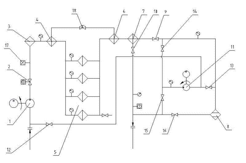
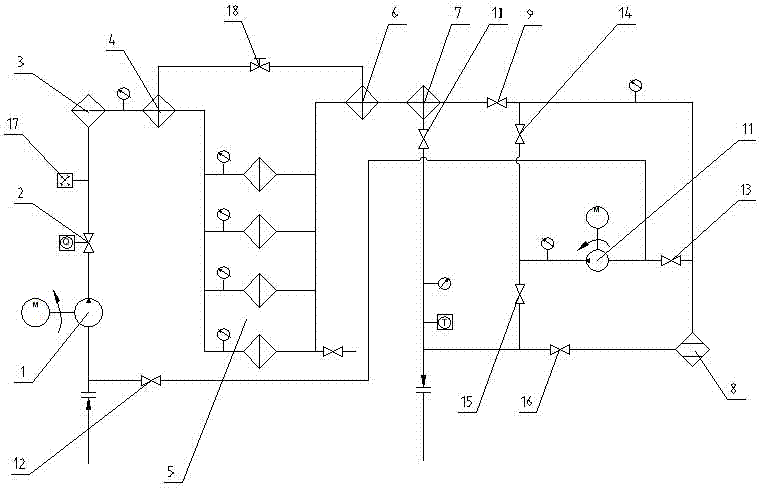
[0014] The present invention will be further described below in conjunction with accompanying drawing. As shown in the figure, a large-flow flushing device includes a main oil pump 1, a flow control valve 2, a coarse filter 3, a first heater 4, and a filter composed of four filters connected in sequence through the main oil pipeline. group 5, second heater 6, third heater 7 and fine filter 8; a first valve 9 is provided between the third heater 7 and the fine filter 8, and there is a The pipeline provided with the second valve 10 leads to the oil outlet; an auxiliary oil pipeline with an auxiliary oil pump 11 is connected in parallel at both ends of the main oil pipeline, and the auxiliary oil pipeline is located on the oil inlet of the auxiliary oil pump 11. There is a third valve 12 at the position between the port and the oil inlet of the main oil circuit, and the pipes with the fourth valve 13 and the fifth valve 14 are respectively provided on the pipelines of the oil inl...


PUM


Abstract

The invention relates to a high-flow flushing device which comprises a main oil pipeline and an auxiliary oil pipeline, wherein the main oil pipeline is provided with a main oil pump; the auxiliary oil pipeline is provided with an auxiliary oil pump; the main oil pipeline and the auxiliary oil pipeline are linked with each other; various filters, heaters and other protecting devices and valves are serially connected to the main oil pipeline; a plurality of pipelines with valves are linked with the auxiliary oil pipeline; and the valves are controlled to open and close, thereby achieving various flushing and filtering purposes. The high-flow flushing device has the beneficial effects that the high-flow flushing device can be used for shortening the flushing time for the steam turbine oil, ensuring the flushing quality of a steam turbine oil system, controlling and promoting the cleanness of turbine oil, and improving a working condition of a project for flushing and purifying the steam turbine oil.

Description

technical field [0001] The invention relates to a flushing device, in particular to a special oil purification equipment with large flow rate and high purification efficiency, which is suitable for pipeline oil flushing and regular filtration and purification of oil. Background technique [0002] The flushing of the turbine oil system is a very important link in the construction of the generating set of the power plant. The quality of the oil is directly related to the safe operation of the turbogenerator set. [0003] When flushing the traditional steam turbine oil system, some chemicals are added, which will cause secondary pollution and other effects on the system pipeline. The traditional oil system has a long flushing period. For example, a new unit in a power construction company needs to be advanced 2-3 months, and a unit overhaul needs more than ten days. Contents of the invention [0004] Purpose of the invention: The purpose of the present invention is to provi...

Claims


Application Information

Patent Timeline
Patent Type & Authority Applications(China)
IPC IPC(8): B08B9/032B08B13/00
Inventor 王庆生
Owner ZHENJIANG KENENG ELECTRIC POWER EQUIP
Why Eureka
Try Eureka