Robot traveling device with liftable frame

A walking device and robot technology, applied in the field of robots, can solve problems such as safety accidents, damage, and loss of control of robot walking, and achieve the effect of stable walking and strong obstacle-surmounting ability.

Inactive Publication Date: 2012-03-28
GUANGZHOU UNIVERSITY
View PDF5 Cites 34 Cited by
  • Summary
  • Abstract
  • Description
  • Claims
  • Application Information

AI Technical Summary

Problems solved by technology

The above-mentioned utility model patent scheme uses the motor as the power and adopts the four-wheel independent drive mode, which provides convenient conditions for the control of the robot's walking, but obviously has the following shortcomings: 1. Because the walking speed of the robot is usually not like that of an ordinary vehicle So fast, so for the scheme that has adopted four-wheel independent drive, its trapezoidal linkage steering mechanism is redundant; 2. The frame and wheels lack suspension, which is for robots walking on very complex terrain features. Obviously, there are many negative effects. For example, the precision instruments installed on the robot may not work properly or even be damaged due to severe vibration. For example, the eyes of the robot, that is, the camera, will blur the image due to severe vibration, which will affect the robot’s ability to recognize the surrounding environment. Accurate judgment may even lead to safety accidents; 3. The height of the frame from the ground remains unchanged. When obstacles are higher than the chassis, one or several vehicles will be suspended in the air and unable to walk, especially in the process of fast walking. When one side of the chassis is jacked up, the robot's walking will be out of control, and in severe cases, it may even cause the car to roll over

Method used


Image

  • Robot traveling device with liftable frame
  • Robot traveling device with liftable frame
  • Robot traveling device with liftable frame

Examples


Embodiment 1

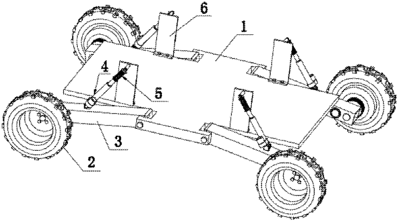
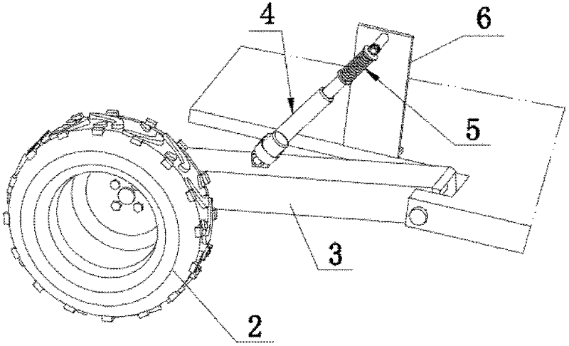
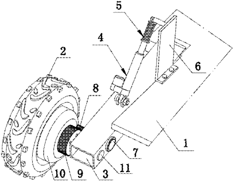
[0021] see Figure 1 ~ Figure 3 , in this example, the described vehicle frame 1 is a rectangular board, all has a rectangular cut-out part along the longitudinal direction at the four corners of this rectangular board, the end of each rectangular cut-out part is respectively connected with one of the independent suspension One end of the cantilever 3 is hinged, and the axis of the cantilever 3 is located in the vertical plane of the vehicle frame 1 ; the other end of each cantilever 3 is hinged to the axle 11 of a wheel 2 . The upper head of the shock absorber in the independent suspension is hinged on the support plate 6 fixed on the vehicle frame 1, and the lower head is hinged on the middle part of the cantilever 3. see Figure 4 ~ Figure 6 , the shock absorber is composed of an electric push rod 4 and a double-acting cylindrical shock absorber 5 coaxially arranged in series at the end of the push rod 4-2 of the electric push rod 4, wherein the two-way acting The cylindr...

Embodiment 2

[0023] This embodiment is improved on the basis of Embodiment 1, and the improvement is that the coil spring 5-3 of the coil spring damper is arranged in the cylinder 5-4. see Figure 7 , the piston 5-2 at one end of the piston rod 5-1 stretches into and fits in the cylinder 5-4, one end of the piston 5-2 is against the end cover 12, and the other end is provided with a coil spring 5-3, The other end of the helical spring 5-3 is against the bottom of the cylinder 5-4.

Embodiment 3

[0025] The difference between this embodiment and Embodiment 1 is that the double-acting cylindrical shock absorber 5 in this example is a hydraulic damping type shock absorber. see Figure 8 and Figure 9, the cylinder 5-4 is coaxially provided with an inner cylinder 14, the annular space between the inner cylinder 14 and the cylinder 5-4 is an oil storage area 16, and the bottom of the inner cylinder 14 communicates with the oil storage area 16 . The piston 5-2 at one end of the piston rod 5-1 stretches into and movably fits into the inner cylinder 14, and the piston 5-2 is provided with two flow valves 17, which are one-way flow valves with two opposite directions. Valve: the bottom of the inner cylinder 14 is provided with a partition 15 that blocks the inner cylinder 14, and the partition 15 is provided with two compensation valves 18, and these two compensation valves 18 are also two one-way valves with opposite directions. End caps 12 and oil seals are provided at th...


PUM


Abstract

The invention relates to a robot traveling device with a liftable frame. The traveling device is provided with a frame (1), four wheels (2), independent suspension brackets and a motor driving device, wherein each independent suspension bracket and the motor driving device are arranged between each wheel (2) and the frame (1); each independent suspension bracket consists of a cantilever (3) and adamper; the axis of the cantilever (3) is positioned in a longitudinal vertical plane of the frame (1), one end of the cantilever (3) is hinged with the frame (1), and the other end of the cantilever(3) is hinged with an axle (11) of the wheels (2); the lower end of the damper is hinged with the middle part of the cantilever (3), and the upper end of the damper is hinged with the frame (1); and the traveling device is characterized in that: the damper consists of an electric push rod (4) and a bidirectional telescopic damper (5) which is coaxially and serially arranged on the end part of a push rod (4-2) of the electric push rod (4). The traveling device has the advantages of high obstacle surmounting capacity and stable and safe traveling.

Description

technical field [0001] The invention relates to a robot, in particular to a walking device of the robot. Background technique [0002] It plays an important role in dangerous operating environments such as emergency rescue, fire, and field detection. From the perspective of the working space of robots, robots are divided into ground robots, underwater robots and aerial robots, among which ground robots are the most widely used. Ground robots are further divided into wheeled and tracked, both of which have their own advantages. Tracked robots are widely used due to their strong face-to-face adaptability and strong climbing ability, but they walk slowly and clumsily. Wheeled robots have aroused the interest of researchers for their advantages of lightness, flexibility and speed. The utility model patent with the publication number CN2717789 discloses a "four-wheel drive wheeled mobile robot mobile vehicle", which is essentially a ground robot walking device, which includes ...

Claims


Application Information

Patent Timeline
Patent Type & Authority Applications(China)
IPC IPC(8): B62D63/02B60G17/00
Inventor 黄文恺陈虹唐连章刘晓初
Owner GUANGZHOU UNIVERSITY
Why Eureka
Try Eureka