Space robot orbit tool replacing device

A space robot and changer technology, applied in the direction of tools, manufacturing tools, manipulators, etc., can solve the problems of large pose tolerance, high quality, poor reliability of space operations, etc., to achieve the effect of integration

Active Publication Date: 2012-03-28
HARBIN INST OF TECH
View PDF7 Cites 12 Cited by
  • Summary
  • Abstract
  • Description
  • Claims
  • Application Information

AI Technical Summary

Problems solved by technology

[0006] In order to solve the problems of poor space operation reliability, inability to realize large pose tolerance, high power consumption, large mass, and large volume in

Method used


Image

  • Space robot orbit tool replacing device
  • Space robot orbit tool replacing device
  • Space robot orbit tool replacing device

Examples


specific Embodiment approach 1

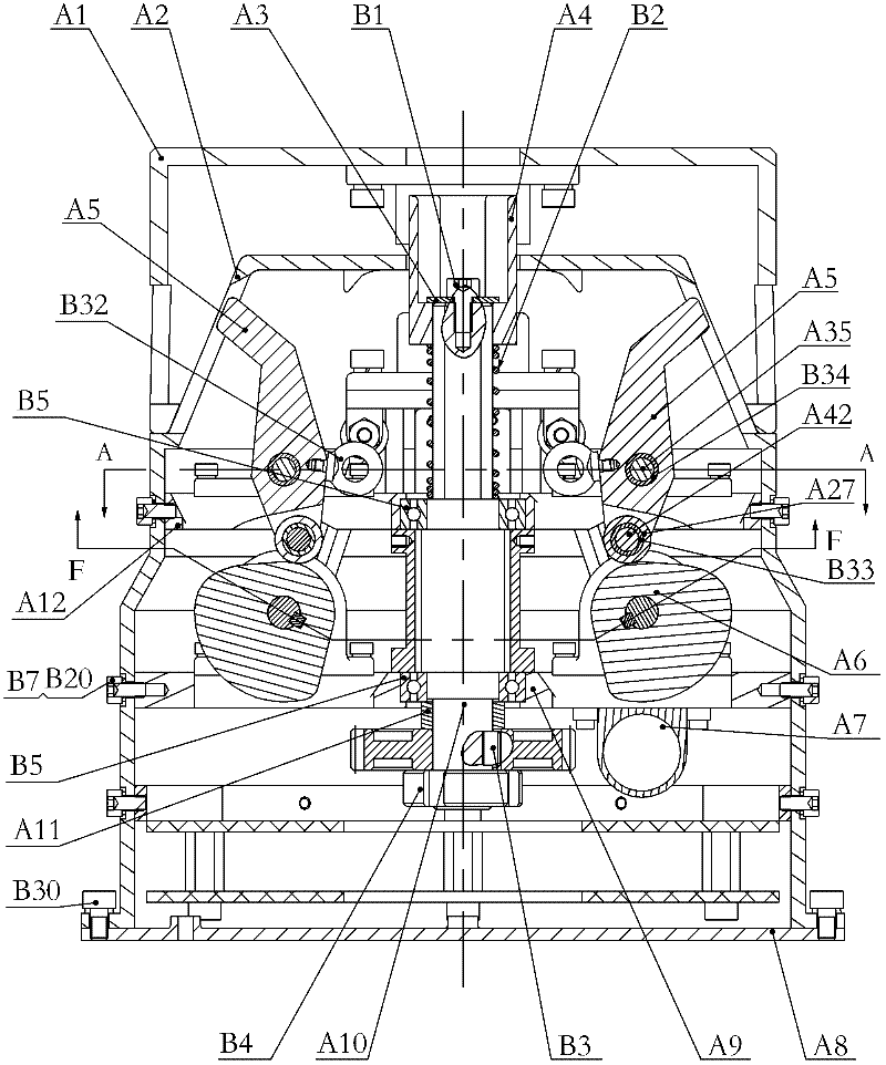
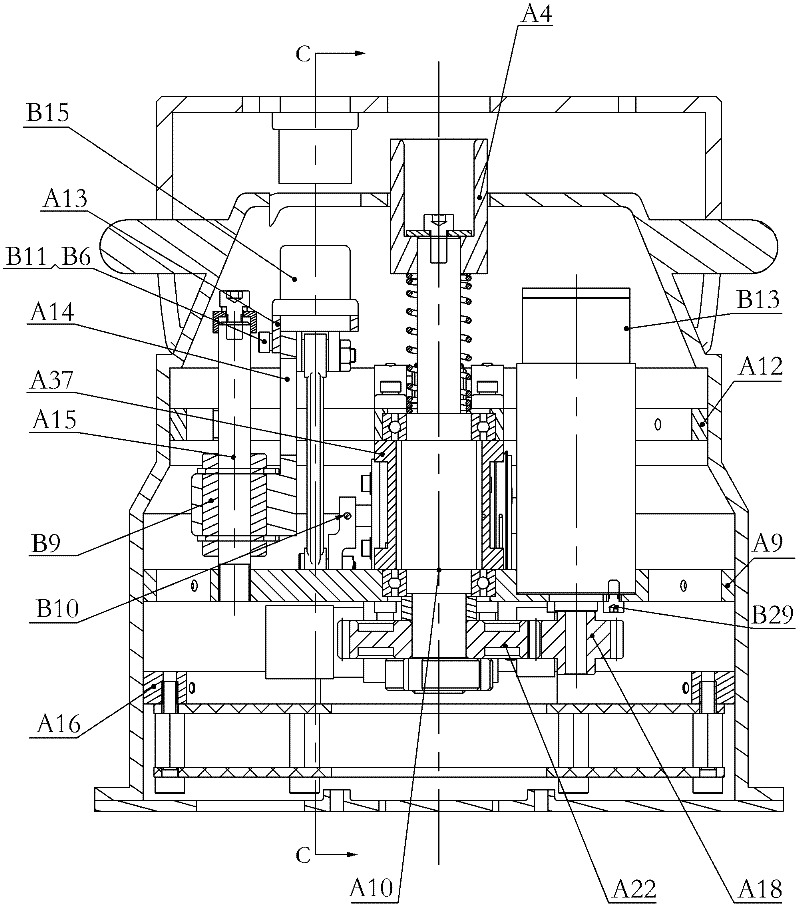
[0020] Specific implementation mode one: as Figure 1-8 As shown, the space robot rail tool changer described in this embodiment includes a housing A2, a bottom end cover A8, a lower support ring A9, an upper support ring A12, a circuit board support frame A16, an electrical system, a first drive system and The second set of drive system, the upper support ring A12, the fixing frame A37, the lower support ring A9, and the circuit board support frame A16 are installed in the housing A2 from top to bottom, the electrical system, the first set of drive system and the second set of drive system The system is placed in the housing A2, the electrical system is placed on the circuit board support frame A16, and the lower end surface of the housing A2 is connected to the bottom end cover A8 (through the screw B30);

[0021] The first drive system includes a first input device, a first transmission device and a first output device, the first input device is the first motor B13 with a p...

specific Embodiment approach 2

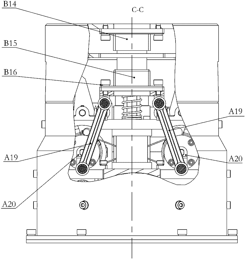
[0026] Specific implementation mode two: as Figure 1-8 As shown, the pushing stroke of the locking finger A5 in this embodiment can press the tool end interface A1; in the remote stroke of the locking finger A5, the cam A6 can idle to realize the docking of the electrical connector interface. Other components and connections are the same as those in the first embodiment.

specific Embodiment approach 3

[0027] Specific implementation mode three: as Figure 1-8 As shown, the limit switch of the second drive system described in this embodiment adopts Hall sensor B35, and Hall sensor B35 is glued to the support block A23 above the bearing seat A24 by glue, and the magnet steel B36 is embedded in the cam length. On the side of the shaft gear A21, the second drive system uses the potentiometer B40 for absolute position sensing, and the potentiometer B40 is soldered on the PCB. Other components and connections are the same as those in the first embodiment.


PUM


Abstract

The invention relates to a space robot orbit tool replacing device, which belongs to the field of space robot on-orbit service and aims at solving the problems that the existing orbit tool replacing device has poor space operation reliability, the great pose tolerance can not be realized, the power consumption is high, the mass is high, and the like. For the mechanical transmission, a motor of a first set of driving system is used for driving a gear, a transmission shaft is driven by the gear, in addition, the function is realized through the butt joint of a screw bolt sleeve arranged on the transmission shaft and a screw bolt head arranged at the other end of the transmission shaft. For electric transmission, a motor of a second set of driving system is used for driving the gear, a cam long shaft is driven by the gear, in addition, the moment on the cam long shaft is transferred to a cam short shaft through a steel wire, and two parts of an electric connector are in butt joint through a slider-crank mechanism fixedly arranged on the cam long shaft and the cam short shaft. The tool end locking adopts the kinematics coupling mode, and before the butt joint realization of the electric connector, a locking finger is driven by a cam to realize the locking of the tool end. The butt joint surface of the orbit tool replacing device and a replaceable tail end manipulator is a conical surface, and great pose tolerance capability can be realized.

Description

technical field [0001] The invention relates to a space robot track tool changer, which belongs to the field of space robot on-orbit service. Background technique [0002] With the advancement of technology, human activities are constantly expanding into space. According to statistics, an average of 80 to 130 satellites are launched each year in the world, but 2 to 3 satellites fail to be put into orbit correctly, and 5 to 10 of the satellites that are put into orbit correctly fail at the beginning of their life, which leads to huge economic loss. In order to recover losses as much as possible, various countries are researching space robot on-orbit service technology for the purpose of satellite maintenance, life extension and space junk removal by means of space robots. [0003] However, the complexity of space operations determines that a single end tool cannot complete all on-orbit tasks. Therefore, it is necessary to develop a multi-tool system to adapt to different ta...

Claims


Application Information

Patent Timeline
IPC IPC(8): B64G4/00B25J19/00
Inventor 刘宇刘奇坤刘宏蒋再男韩锋
Owner HARBIN INST OF TECH
Why Eureka
Try Eureka