Pollutant separation device of rainwater and sewage pipeline

A technology for separating devices and pollutants, which is applied in the fields of grease/oily substance/float removal device, water/sewage treatment, water/sludge/sewage treatment, etc., which can solve problems such as affecting operation and easy clogging of filters.

Inactive Publication Date: 2012-03-28
JIANGSU UNIV
View PDF5 Cites 12 Cited by
  • Summary
  • Abstract
  • Description
  • Claims
  • Application Information

AI Technical Summary

Problems solved by technology

At present, the commonly used method for separating solid waste from sewage is to set a filter screen perpendicular to the direction of sewage flow. This method is simple and easy to achieve the separation effect on solid waste, but the filter screen is easily blocked, which affects the operation.

Method used


Image

  • Pollutant separation device of rainwater and sewage pipeline
  • Pollutant separation device of rainwater and sewage pipeline
  • Pollutant separation device of rainwater and sewage pipeline

Examples


Embodiment Construction

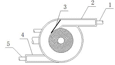
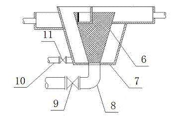
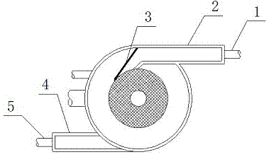
[0009] Attached below figure 1 and attached figure 2 The present invention is further described:

[0010] As shown in the accompanying drawings, the invention is mainly composed of an inlet channel 2, an overflow weir 3, an outlet channel 4, an inner conical screen 6, an outer conical cylinder 7, a slag discharge pipe 8 and a sewage pipe 10, and the overflow weir is composed of 3. Connect the water inlet channel 2 and the inner conical screen 6, and have the same height and tangent to the inner conical screen 6. The outlet channel 4 is tangent to the outer conical cylinder 7, and the channel bottom of the outlet channel 4 is slightly lower than the channel bottom of the inlet channel 2. A slag discharge valve 9 and a sewage valve 11 are installed in the horizontal section of the slag discharge pipe 8 and the sewage pipe 10. The slag discharge valve 9 is opened regularly according to the actual situation, and the sewage valve 11 is normally open and closed when necessary. O...


PUM


Abstract

The invention discloses a pollutant separation device of a rainwater and sewage pipeline, and the device comprises a water inlet pipe, a water inlet channel, an overflow weir, a water outlet channel, a water outlet pipe, an inner conical screen mesh, an outer conical cylinder body, a deslagging pipe, a deslagging valve, a sewage pipe and a sewage valve. The pollutant separation device is combined with the rotational flow principle for introducing municipal sewage and antecedent runoff in rainy days into the inner conical screen mesh through the diversion effect of the overflow weir, solid wastes in the sewage are separated through the interception effect of the inner conical screen mesh, and the pollutant separation device aims at reducing the blockage of the sewage pipeline and reducing the treatment load of a sewage treatment plant. Simultaneously, the device realizes the power-free backwash effect and can effectively prevent the partial blockage of the inner conical screen mesh.

Description

technical field [0001] The invention relates to a pollutant separation device for rainwater and sewage pipelines. According to the International Patent Classification (IPC), it is classified into fixed building department, building branch, water supply and drainage, and sewer and sewage well. Background technique [0002] With the continuous acceleration of the urbanization process, the impervious area gradually increases, which makes the instantaneous rainwater flow in some cities increase during the rainy season, and the blockage of the pipeline causes the phenomenon of water accumulation and even the danger of flooding. In view of the fact that most of the pipelines are currently combined pipelines, the main causes of pipeline blockage are solid waste from municipal sewage, tree branches and leaves from rainwater and road waste. The existence of solid waste in sewage, on the one hand, will affect the transmission efficiency of the pipeline, and on the other hand, it will ...

Claims


Application Information

Patent Timeline
Patent Type & Authority Applications(China)
IPC IPC(8): E03F5/14
Inventor 解清杰何锋陶明清
Owner JIANGSU UNIV
Why Eureka
Try Eureka