Low-temperature energy saving generation system

An energy-saving power generation and low-temperature technology, which is applied in the direction of engine components, machines/engines, mechanical equipment, etc., can solve problems that affect the ecological environment and life safety, high electricity price costs, and difficult construction, etc., to achieve improved cycle power generation efficiency, simple structure, well-designed effects

Inactive Publication Date: 2012-03-28
STATE GRID HENAN ELECTRIC POWER COMPANY ZHENGZHOU POWER SUPPLY
View PDF0 Cites 2 Cited by
  • Summary
  • Abstract
  • Description
  • Claims
  • Application Information

AI Technical Summary

Problems solved by technology

At present, the commonly used power generation methods include thermal steam power generation, hydropower generation and nuclear power generation. Among them, thermal steam power generation consumes a large amount of coal, resulting in higher and higher electricity costs. In addition, coal mining is highly dangerous, and mining disasters occur endlessly. Life benefits and economic interests are damaged, and coal burning also pollutes the environment, which in turn pollutes people's health
Hydropower generation uses natural water resources, and the cost is relatively low. However, the construction of hydropower stations is difficult and destroys the ecological environment in a certain area; nuclear power generation requires high-level protective measures and high construction costs. Once nuclear fuel leaks, serious Affect the ecological environment and people's life safety

Method used


Image

  • Low-temperature energy saving generation system
  • Low-temperature energy saving generation system

Examples


Embodiment Construction

[0014] Below in conjunction with accompanying drawing, the present invention will be further described:

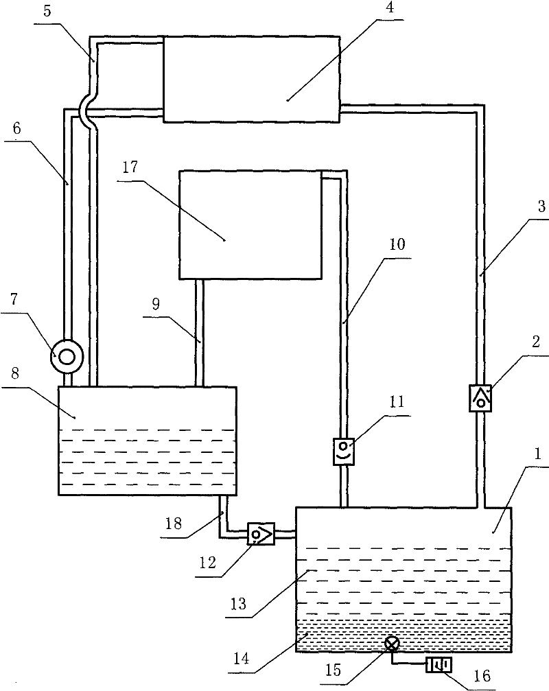
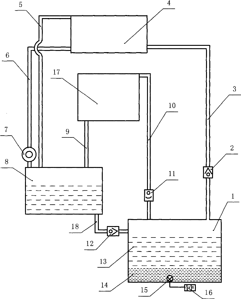
[0015] see figure 1 , the names of the components represented by the serial numbers in the figure are: 1-energy chamber, 2-one-way flow valve, 3-upper water pipe, 4-high level chamber, 5-air guide pipe, 6-down water pipe, 7-hydraulic generator, 8-water source warehouse, 9-cooling pipe, 10-exhaust pipe, 11-one-way exhaust valve, 12-one-way flow valve, 13-water, 14-low boiling point high-density liquid, 15-heater, 16- External temperature control switch, 17-cooling chamber, 18-communicating pipe.

[0016] A low-temperature energy-saving power generation system, comprising an energy bin 1, a high-level bin 4, a water turbine generator 7, and a water source bin 8. The energy bin 1 communicates with the high-level bin 4 through an upper water pipe 3, and the upper water pipe 3 is provided with a single to the circulation valve 2; the high position chamber 4 communicates with ...


PUM


Abstract

The invention discloses a low-temperature energy saving generation system. An energy bin is communicated with a high bin through a water feeding pipe; the water feeding pipe is provided with a one-way flow valve; the high bin is communicated with a water source bin through a water draining pipe; the water draining pipe is provided with a hydraulic generator; the water source bin is communicated with the energy bin through a communication pipe; the communication pipe is provided with a one-way flow valve; the bottom of the water source bin is level with or higher than the top of the energy bin; a heater is arranged in the energy bin and connected with an external temperature control switch; and an air guiding pipe is arranged between the high bin and the water source bin. In the invention, the liquid with a low boiling point is evaporated by heating to form a steam pressure, and the aqueous solution is forced to rise to the high bin to form potential energy; and the aqueous solution inclines downwards under the gravity so as to push the hydraulic generator to generate electricity. As the liquid with the low boiling point has a relatively high density, the liquid is injected into the water source bin through low-temperature condensation and flows into the energy bin in a circulation process to realize circular use, thus the loss of the liquid is avoided, the use amount is relatively small, and the cost is relatively low.

Description

Technical field: [0001] The invention relates to a power generation device, in particular to a low-temperature energy-saving power generation system, which belongs to the technical field of energy development. Background technique: [0002] With the development of global industry, energy is becoming less and less, and energy has become a bottleneck for the development of industrial countries. At present, the commonly used power generation methods include thermal steam power generation, hydropower generation and nuclear power generation. Among them, thermal steam power generation consumes a large amount of coal, resulting in higher and higher electricity costs. In addition, coal mining is highly dangerous, and mining disasters occur endlessly. Life benefits And economic interests are damaged, coal burning also pollutes the environment, and then pollutes people's health. Hydropower generation uses natural water resources, and the cost is relatively low. However, the construct...

Claims


Application Information

Patent Timeline
Patent Type & Authority Applications(China)
IPC IPC(8): F03B13/00
Inventor 张伟政钟浩吕利敏孙卉
Owner STATE GRID HENAN ELECTRIC POWER COMPANY ZHENGZHOU POWER SUPPLY
Why Eureka
Try Eureka