Multistage differential pumped ultrahigh vacuum sample transmission mechanism

An ultra-high vacuum, sample transfer technology, applied in the direction of analytical materials, instruments, etc., can solve the problems of low work efficiency, lack of ownership, long time, etc., to achieve the effect of improving experimental efficiency and reliability

Inactive Publication Date: 2012-03-28
大连齐维科技发展有限公司
View PDF4 Cites 2 Cited by
  • Summary
  • Abstract
  • Description
  • Claims
  • Application Information

AI Technical Summary

Problems solved by technology

The problem with setting up the sampling chamber is that the atmosphere must be opened frequently, and it takes a long time to reach the pressure balance of the ultra-high vacuum chamber every time, and the work efficiency is low.
[0003] Realizing the high-speed transfer of samples between the atmosphere and the ultra-high vacuum environment is not only the demand of basic scientific research and the semiconductor industry, but also the high efficiency of aerospace development. It has been expected to be a major issue to be solved. At present, my country does not have this technology.

Method used


Image

  • Multistage differential pumped ultrahigh vacuum sample transmission mechanism
  • Multistage differential pumped ultrahigh vacuum sample transmission mechanism
  • Multistage differential pumped ultrahigh vacuum sample transmission mechanism

Examples


Embodiment Construction

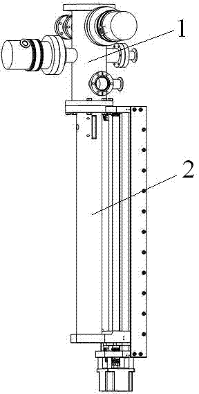
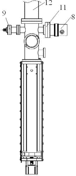
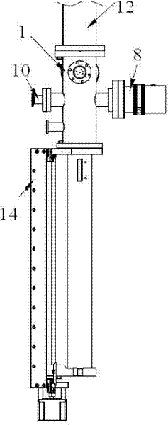
[0017] Such as figure 1 The four-stage differential pumping ultra-high vacuum sample transfer mechanism shown in -3 is composed of a differential pumping mechanism 1 and a sample transfer rod driver 2, and the differential pumping mechanism 1 is as follows: Figure 4 As shown, the U-shaped sealing ring 6 is used to separate the U-shaped sealing ring in the cavity and is supported by the spacer ring 7 to form three spaces, namely, the first differential pump 3, the second differential pump 4 and the third differential pump 5. Each differential The pumping space has an independent vacuum obtaining mechanism and detection mechanism 9, and the first-stage differential pumping space is fixedly connected with the sample transfer rod driver through a flange. The blue is connected with the ultra-high vacuum chamber, and the vacuum obtaining ability of each differential pumping space is enhanced sequentially. The highest-level differential pumping space is fixedly connected with the ul...


PUM


Abstract

The invention relates to the field of ultrahigh vacuum equipment development, in particular to a multistage differential pumped ultrahigh vacuum sample transmission mechanism, which consists of a differential pumping mechanism and a sample transmission rod driver, wherein the differential pumping mechanism is that a cavity is separated into 2 to 3 spaces by seal rings; each space has independent vacuum acquisition mechanism and detection mechanism; a first-stage differential pumping space is fixedly connected with the sample transmission rod driver; the vacuum acquisition capacities of the differential pumping spaces are improved in turn from the sample transmission rod driver end to the ultrahigh vacuum cavity end; the highest stage of differential pumping space is fixedly connected with the ultrahigh vacuum cavity; and a sample transmission rod of the sample transmission rod driver is inserted in a differential pumping chamber and drives the mechanism to rotate. The multistage differential pumped ultrahigh vacuum sample transmission mechanism realizes high-speed sample transmission between the atmosphere and the ultrahigh vacuum cavity, and greatly improves experiment efficiency and reliability. The invention solves a core technological problem that apparatus in a spacecraft are radiated by spatial cosmic rays, fills up a domestic blank and reaches a world-class level.

Description

technical field [0001] The invention relates to the field of ultra-high vacuum equipment development. Background technique [0002] Ultra-high vacuum technology is the basic environment for the synthesis of new materials, the analysis of physical and chemical properties of materials, and the development of the universe. Picking and placing (transferring) samples between atmospheric and ultra-high vacuum environments is a difficult technique. In order not to destroy the ultra-high vacuum environment, it is generally necessary to set up a sampling chamber between the atmosphere and the ultra-high vacuum chamber. The sampling chamber and the ultra-high vacuum chamber are isolated by a gate valve, and have a separate vacuum acquisition and detection system. When the sampling chamber is at atmospheric pressure, the window can be opened to take and place the sample; after the window is closed, the vacuum acquisition system of the sampling chamber is started, and when the vacuum ...

Claims


Application Information

Patent Timeline
Patent Type & Authority Applications(China)
IPC IPC(8): G01N35/00
Inventor 郭方准
Owner 大连齐维科技发展有限公司
Why Eureka
Try Eureka