
Method for controlling cutting quantity of spiral bevel gear

A technology of spiral bevel gears and control methods, which is applied in general control systems, control/regulation systems, instruments, etc., and can solve problems such as difficulty in forming mathematical models and complex causes of tooth surface quality problems.

Inactive Publication Date: 2012-03-28
TIANJIN UNIVERSITY OF TECHNOLOGY
View PDF2 Cites 10 Cited by
  • Summary
  • Abstract
  • Description
  • Claims
  • Application Information

AI Technical Summary

Problems solved by technology

The causes of tooth surface quality problems are complex, and it is difficult to form a unified mathematical model

Method used


Image

  • Method for controlling cutting quantity of spiral bevel gear
  • Method for controlling cutting quantity of spiral bevel gear
  • Method for controlling cutting quantity of spiral bevel gear

Examples


Embodiment 1

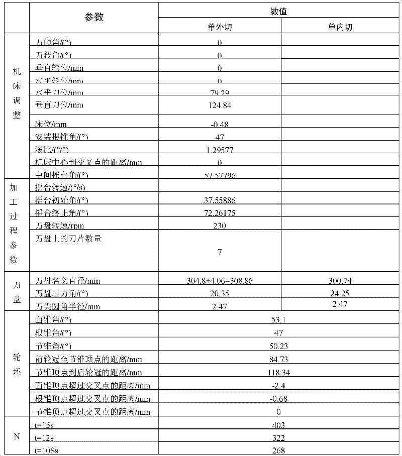
[0043] In this example, when the cutting amount of the high-speed cutting machine tool is less than 0.11 mm, the vibration is small, and the surface finish of the processed tooth surface is high. It is necessary to determine the processing time when the cutting amount is less than 0.11mm. The known parameters are shown in Table 1:

[0044] Table 1 Relevant parameters and calculated values ​​of cutting inserts

[0045]

[0046] In the hobbing process of the spiral bevel gear, a disc milling cutter is used, and the cutter head speed n and the number of blades m are known, and the processing time t and the cradle speed w need to be determined.

[0047] 1) Use the solid modeling in the CAM software Solidworks to establish the model of the blade and the gear blank, determine the reasonable start angle and end angle of hobbing, and calculate the swing angle range of the cradle q=72.26175-37.55886.

[0048] 2) Segment the required time. The cutting time determined in this example...


PUM


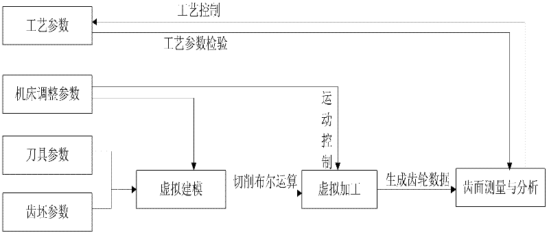
Abstract

A method for controlling the cutting quantity of a spiral bevel gear solves the problem of adjusting processing technology parameters such as rotating speed of a cutter, number of blades on the cutter, processing time, and the like according to the cutting quantity and the precision of a tooth surface. The method comprises a cutting simulation method in the hobbing process of the spiral bevel gear and processing parameter methods for controlling a chipping simulation method and the cutting process. On the basis of a hobbing simulation method, the processing technology parameters, tool adjusting parameters, tool adjusting parameters and cutter and tooth billet parameters are adopted for conducting virtual three-dimensional entity molding, simulating the high-speed cutting process of the gear, and providing the method for controlling the cutting quantity. The method is applied in practical processing.

Description

technical field [0001] The invention belongs to the field of computer-aided manufacturing, and relates to the processing and manufacturing of spiral bevel gears, complex curved surface processing and computer-aided processing methods. Background technique [0002] In recent years, foreign countries have produced the latest series of Phoenix II CNC gear cutting machines and gear grinding machines, and the machining accuracy can be improved by 1 to 2 levels compared with traditional machine tools. As far as the cutting speed is concerned, high-speed dry cutting is used to finish the tooth surface. The cutting speed reaches more than 300m / min, the milling precision reaches 4th and 5th grades, and the tooth surface finish is high. Although this type of CNC machine tool has many advantages, due to its high price, it is difficult to popularize it in the country in the short term. The development of high-speed dry cutting CNC machine tools with independent property rights has becom...

Claims


Application Information

Patent Timeline
Patent Type & Authority Applications(China)
IPC IPC(8): G05B17/02
Inventor 韩佳颖
Owner TIANJIN UNIVERSITY OF TECHNOLOGY
Learn More