Combined-type high-voltage conversion switch

A transfer switch and combined technology, applied in the direction of high voltage/high current switch, electric switch, high voltage air circuit breaker, etc., can solve the problems of reduced work efficiency, long switching time, reduced conductivity, etc., to achieve reduced installation space, huge Economic benefits, simplified and compact structure

Active Publication Date: 2012-03-28
PINGYANG ELECTRIC POWER SUPPLY COMPANY OF STATE GRID ZHEJIANG ELECTRIC POWER
View PDF7 Cites 6 Cited by
  • Summary
  • Abstract
  • Description
  • Claims
  • Application Information

AI Technical Summary

Problems solved by technology

[0003] Chinese patent application 200610154471.3 discloses an outdoor high-voltage dual-power vacuum circuit breaker. This type of vacuum circuit breaker is equipped with a high-voltage dual-power conversion device consisting of a chained double-throw isolating switch on the vacuum circuit breaker. Although this method realizes high-voltage There are electrical interlocking and mechanical interlocking when the dual power supply is automatically switched, which reduces the possibility of two high-voltage feeds at the same time. It is an ideal high-voltage dual power switching device at present, but there are still drawbacks. In the external environment, with the increase of the number of tim

Method used


Image

  • Combined-type high-voltage conversion switch
  • Combined-type high-voltage conversion switch

Examples


Embodiment Construction

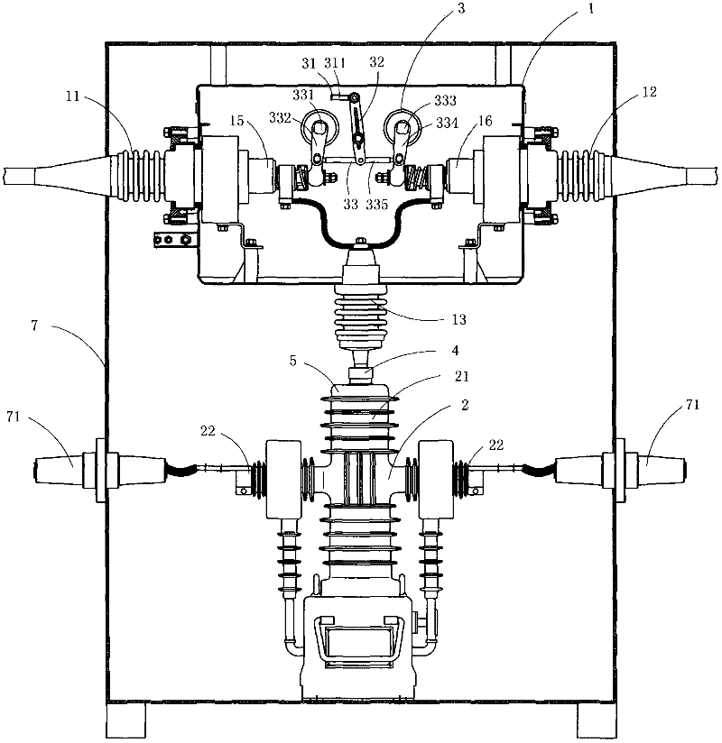
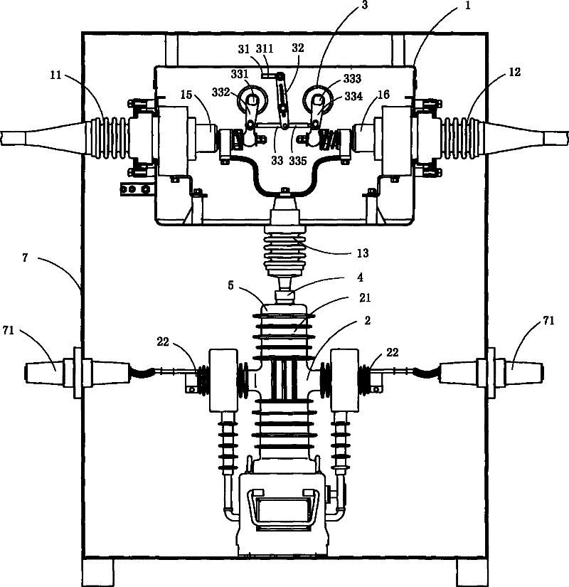
[0018] Fig. 1 is a schematic structural view of the present invention, showing a specific embodiment of the present invention.

[0019] The present embodiment is a combined high-voltage transfer switch, as shown in Fig. 1, comprising an armored casing 7, and a dual power switching device 1 and a vacuum circuit breaker 2 arranged in the armored casing 7; the dual power switching device 1 includes main power terminal 11, auxiliary power terminal 12, outlet terminal 13 and switching operation mechanism 3; the vacuum circuit breaker 2 includes incoming terminal 21, outgoing terminal 22, vacuum arc extinguishing mechanism and operating mechanism.

[0020] The dual power switching device 1 also includes a main vacuum arc extinguishing mechanism 15 electrically connected to the main power terminal 11, and an auxiliary vacuum vacuum arc extinguishing mechanism 16 electrically connected to the auxiliary power terminal 12; the switching operation mechanism 3 includes A driving mechanism...


PUM


Abstract

The invention discloses a combined-type high-voltage conversion switch which comprises a double-power-supply switching device and a vacuum circuit breaker, wherein the double-power-supply switching device comprises a main power supply post, an auxiliary power supply post, a wire outlet column; and the vacuum circuit breaker comprises a wire inlet terminal, a wire outlet terminal, a vacuum extinction mechanism and an operation mechanism. The double-power-supply switching device also comprises a main vacuum extinction mechanism electrically connected with the main power supply post and an auxiliary vacuum extinction mechanism electrically connected with the auxiliary power supply post; the switching operation mechanism comprises a driving mechanism with a driving arm, a lever and an interlocking mechanism which is used for synchronously driving the switch-on and switch-off motions of the main vacuum extinction mechanism and the auxiliary vacuum extinction mechanism; the driving arm in the driving mechanism is connected with one end of the lever in a rotation mode, and the other end of the lever is connected with the interlocking mechanism; and the wire inlet terminal of the vacuum circuit breaker is electrically connected with the wire outlet terminal in the double power supply switching device. According to the invention, the time required for double-power-supply switching is shorter, and the double-power-supply switching is approximate to non-time-difference switching.

Description

technical field [0001] The invention belongs to the technical field of high-voltage dual power switch structure design, and in particular relates to a combined high-voltage transfer switch. Background technique [0002] At present, in order to improve the reliability of power supply, a large number of dual power supply lines (two power supply lines, generally one power system line and one self-contained line) are used in the power supply system. When the power supply of one line fails, the other line supplies power. . For this reason, control devices are needed, and no less than two high-voltage switchgears should be used indoors, and no less than two high-voltage switches on poles should be used outdoors, so as to realize the requirements of selecting power supply lines. This control method not only increases the user's equipment and operating costs, but also poses hidden dangers of power supply accidents. For two or more high-voltage switchgear / column-mounted high-voltag...

Claims


Application Information

Patent Timeline
IPC IPC(8): H01H33/666H01H33/664
Inventor 苏肄鹏
Owner PINGYANG ELECTRIC POWER SUPPLY COMPANY OF STATE GRID ZHEJIANG ELECTRIC POWER
Why Eureka
Try Eureka