
Laminated sheet type ceramic delay line

A delay line and layered technology, applied in the direction of delay lines, electrical components, circuits, etc., can solve the problems of unfavorable system miniaturization, unsuitable communication products, large delay lines, etc., and achieve high reliability and high quality factor , The effect of widening the working frequency band

Inactive Publication Date: 2012-03-28
成都成电电子信息技术工程有限公司
View PDF2 Cites 6 Cited by
  • Summary
  • Abstract
  • Description
  • Claims
  • Application Information

AI Technical Summary

Problems solved by technology

The traditional delay line is large in size, and generally only has a single-layer design. For example, the delay function is realized by using planar folded lines on the circuit substrate, and the performance index of the delay line mainly depends on the length and phase accuracy of the delay line. In order to achieve a certain Delay time, only increase the volume of the device to achieve a longer delay line length, resulting in increased device cost and reduced reliability, which does not meet the trend of communication products developing towards short, small, light and thin
On the other hand, if the system needs to implement different delay functions in multiple groups of signal paths, it is necessary to use multiple groups of delay units, such as a delay line with a single-layer design, because it only has a single output port, it needs Placing a delay line greatly occupies the area of ​​the circuit, which is not conducive to the miniaturization of the system; the delay line with multiple output terminals is generally a planar two-dimensional structure, and the delay unit is composed of capacitors and inductors in the form of discrete devices in the device. Large size and low reliability. If planar folded wires are used to implement each delay unit, in order to avoid electromagnetic coupling interference between folded wires, a certain distance needs to be reserved between adjacent two wires, which will also take up a large amount of time. circuit area

Method used


Image

  • Laminated sheet type ceramic delay line
  • Laminated sheet type ceramic delay line
  • Laminated sheet type ceramic delay line

Examples


Embodiment Construction

[0024] The present invention will be described in further detail below in conjunction with the embodiments and the accompanying drawings, but the embodiments of the present invention are not limited thereto.

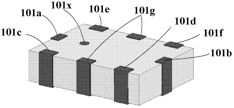
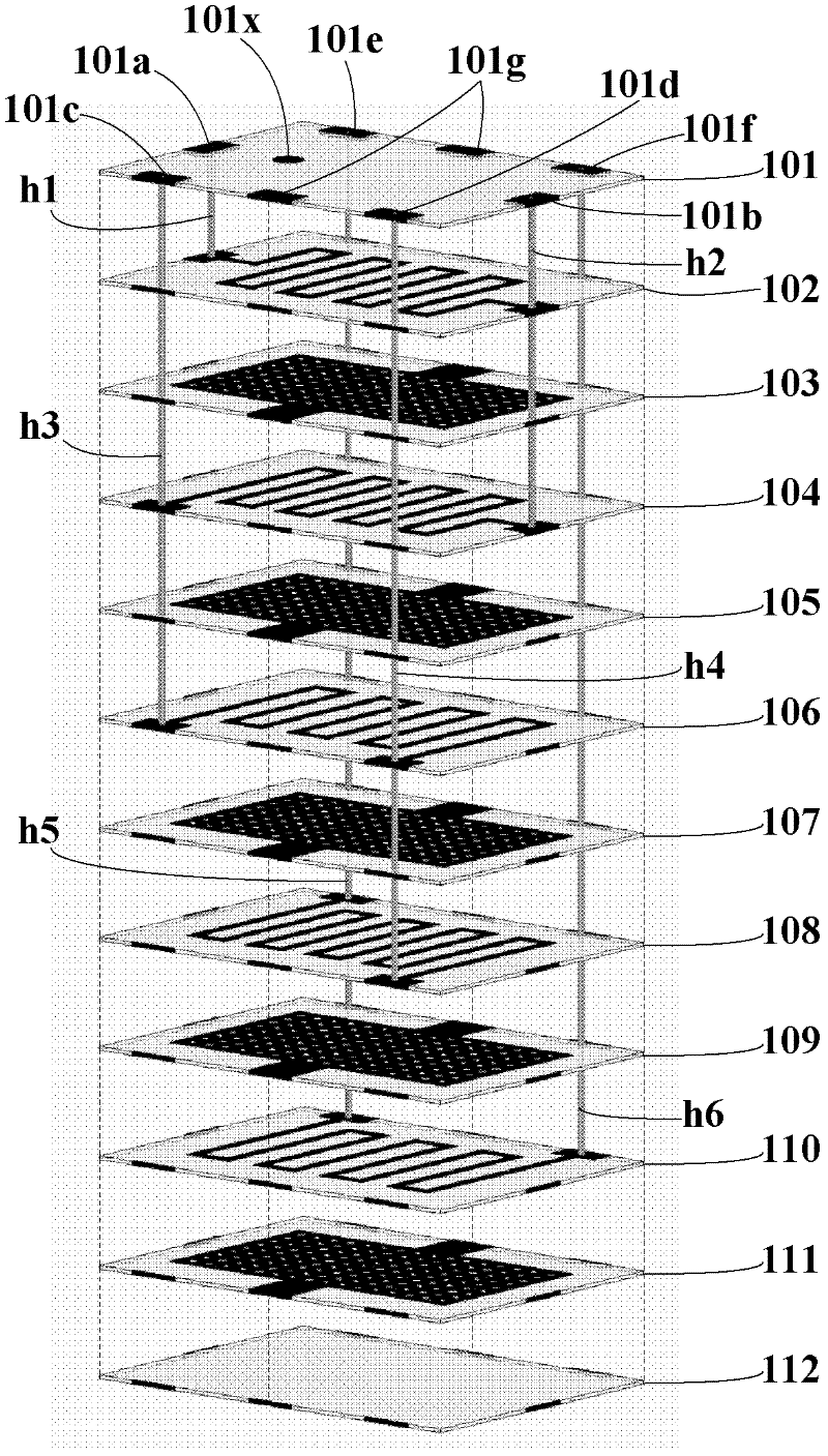
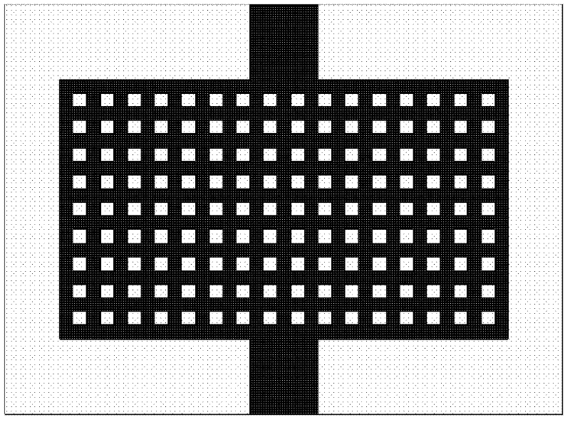
[0025] Such as figure 1 , 2 , 3, the laminated chip ceramic delay line includes 12 layers of chip ceramic media 101, 102, 103, 104, 105, 106, 107, 108, 109, 110, 111, 112; the folded metal Conductive metal is used to print the conductive metal on the top of the sheet-shaped ceramic dielectric layers 102, 104, 106, 108, 110; the grid-like metal layer is printed on the top of the sheet-shaped ceramic dielectric layers 103, 105, 107, 109, 111 with conductive metal; The metallized through hole h1 connects the device signal input end 101a and the input end of the first metal line delay unit, and the metallized through hole h2 connects the first signal output end 101b, the output end of the first metal line delay unit and the second metal line delay unit The input end of the...


PUM


Abstract

The invention relates to a laminated sheet type ceramic delay line, which belongs to the technical field of electronic components. The delay line comprises a plurality of metal wire delay cell laminated bodies and a plurality of metal ground electrode laminated bodies, wherein the plurality of the metal wire delay cell laminated bodies and the plurality of the metal ground electrode laminated bodies are laminated together in a staggered mode; a plurality of the metal wire delay cells are connected in series in turn and are connected to the surface of a device through metallized through holes;and the surface of the device is provided with a signal input end, a plurality of signal output ends, a ground electrode port and a port mark. With the adoption of a low temperature co-fired ceramic (LTCC) technology, a plurality of the metal delay line cells which are connected in series in turn are integrated in a lamination mode, so that the volume and the weight of the delay line are effectively reduced, and the delay line has the characteristics of good insulation property, great merit factors, high self-resonance frequency, wide working bandwidth and the like; and simultaneously, metal delay cells are embedded in a dielectric ceramic body to improve the reliability of the delay line so that the delay line can adapt to various different working environments.

Description

technical field [0001] The invention belongs to the technical field of electronic components, and relates to a delay line, in particular to a laminated delay line with miniaturization, wide frequency band, long delay and integration of multiple sets of taps. Background technique [0002] Delay lines are widely used in more sophisticated oscilloscopes, color TVs, electronic computers, aviation, radar and other fields, and are one of the most commonly used devices in microwave systems. The traditional delay line is large in size, and generally only has a single-layer design. For example, the delay function is realized by using planar folded lines on the circuit substrate, and the performance index of the delay line mainly depends on the length and phase accuracy of the delay line. In order to achieve a certain For the delay time, the only way to increase the volume of the device is to achieve a longer delay line length, resulting in higher device costs and lower reliability, w...

Claims


Application Information

Patent Timeline
IPC IPC(8): H01P9/00
Inventor 徐自强夏红杨邦朝曾志毅唐伟尉旭波李恬
Owner 成都成电电子信息技术工程有限公司
Learn More